
Blood pump

a blood pump and pump body technology, applied in the field of blood pumps, can solve the problems of increasing left ventricular end-diastolic volume and pressure, not being able to know the unassisted heart function, so as to improve the assessment of the status of heart recovery

Active Publication Date: 2022-06-07
ABIOMED EURO
View PDF8 Cites 17 Cited by
  • Summary
  • Abstract
  • Description
  • Claims
  • Application Information

AI Technical Summary

Benefits of technology

This patent aims to improve the control method and device for an intravascular blood pump that can better assess the status of heart recovery. It is designed to help enhance the performance of the blood pump and ensure it runs efficiently. The technical effects include better understanding of heart recovery, improved pump operation, and better overall performance.

Problems solved by technology

While the blood pump is assisting the heart, it is not possible to know the unassisted heart function.
And when the blood pump is switched off flow regurgitation through the cannula occurs so that it is impossible to know about the unassisted heart function.
Regurgitation is particularly a problem of intravascular blood pumps because the blood pump, more specifically the pump's cannula, extends through a cardiac valve, e.g. the aortic valve, thereby creating an open path through the cardiac valve, which backflow into the heart when the blood pump is not driven.
When the blood pump is switched off and if the heart still works insufficiently, the no longer assisted ventricle would significantly dilate so that not enough blood volume is ejected from the ventricle during the systolic phase, leading to an increase in left ventricular end-diastolic volumes and pressures.
This may result in a setback of the therapy of several days.

Method used


Image

  • Blood pump
  • Blood pump
  • Blood pump

Examples


Embodiment Construction

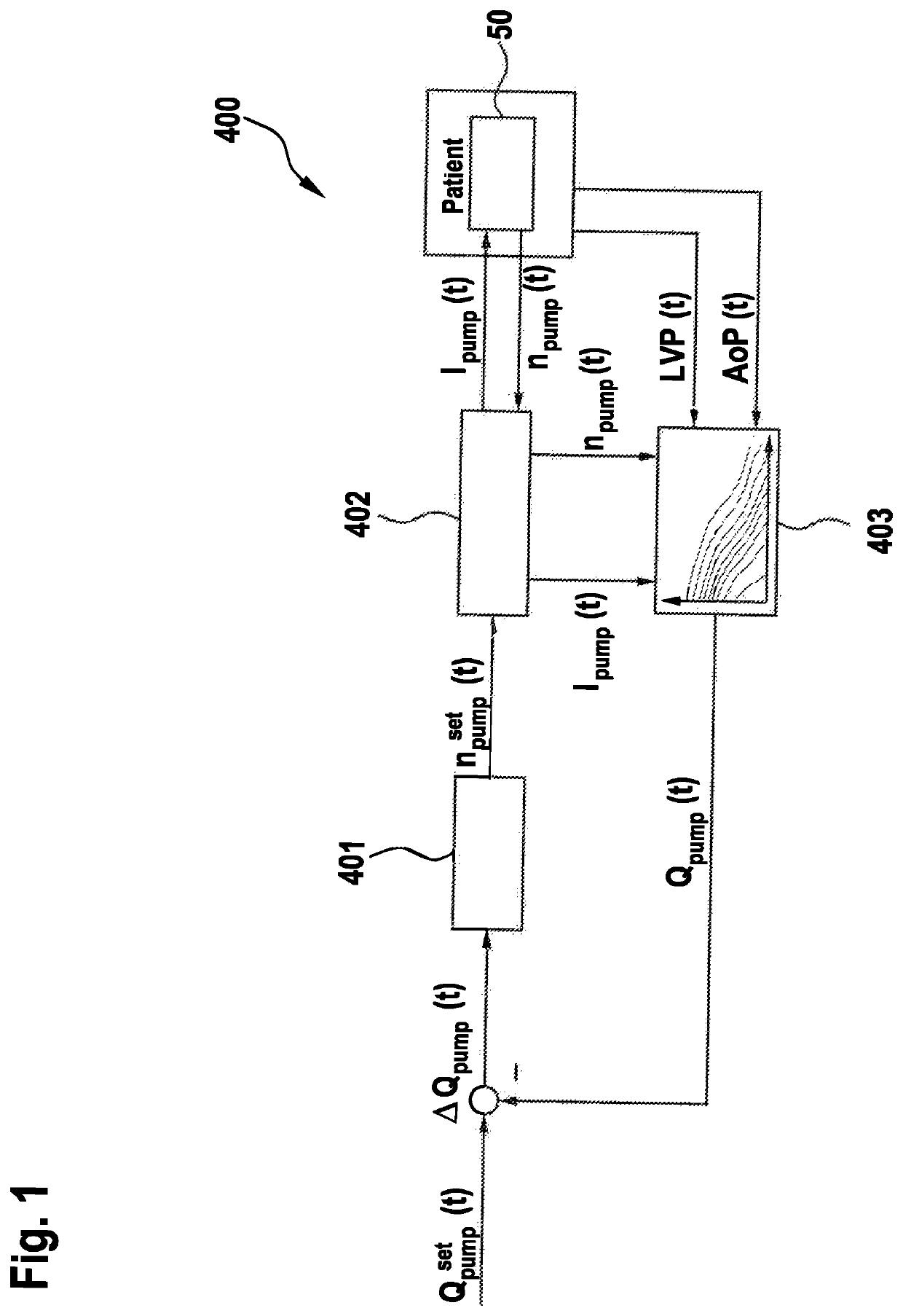
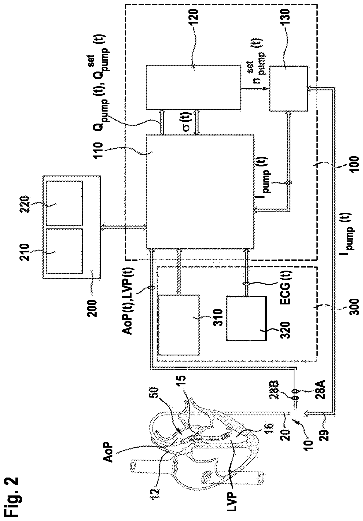
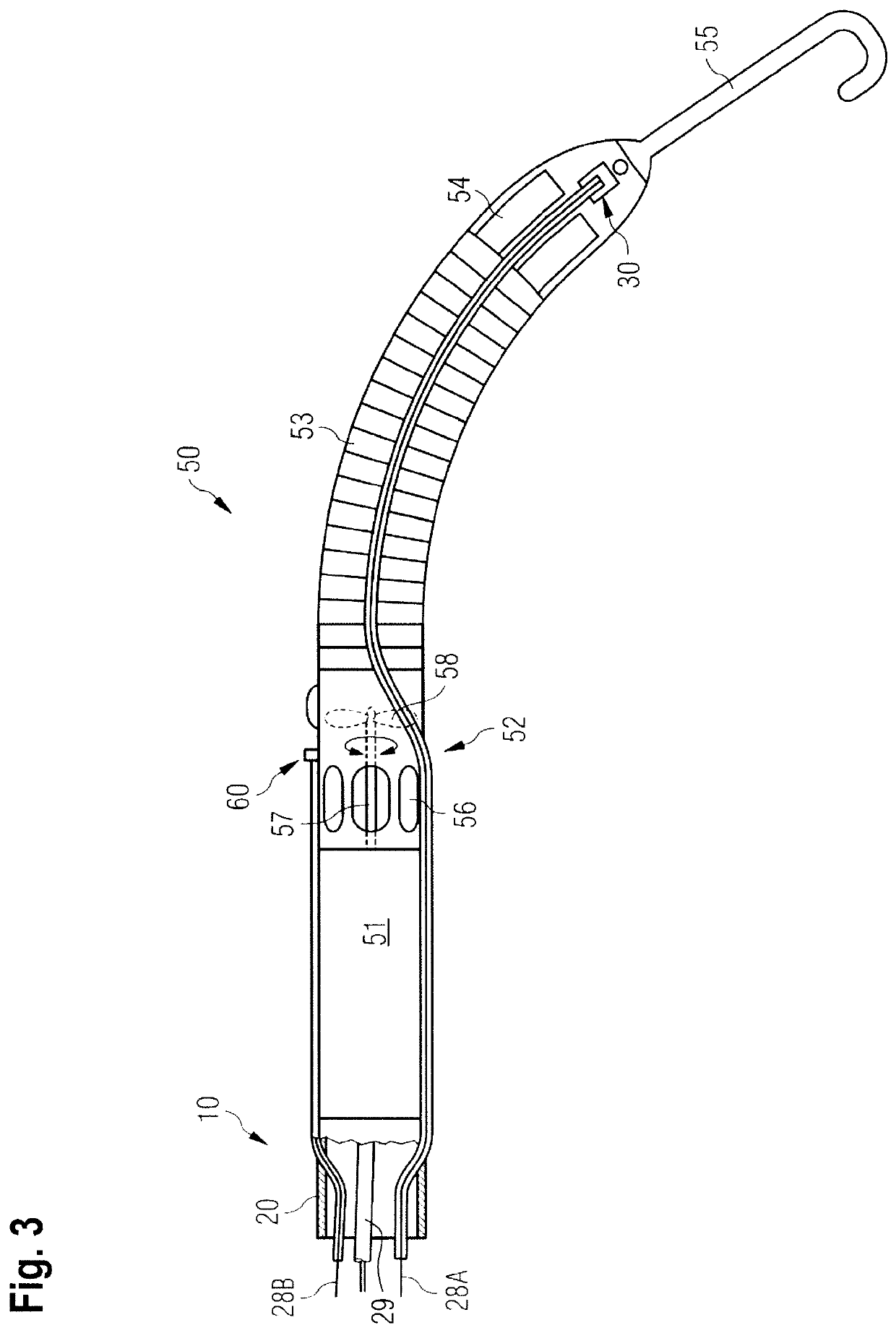
[0072]FIG. 1 shows a block diagram which is an example of the feedback control loop for blood flow control realized as a cascade control system. The control loop comprises an outer controller 401 and an inner controller 402. The outer controller 401 is embedded in outer control loop and regulates a generated blood flow Qpump(t) of e.g. the blood pump 50 shown in FIG. 3 by comparing a blood flow command signal Qpumpset(t) with the generated blood flow Qpump(t), and by setting the set-point of the inner control loop, namely the speed command signal npumpset(t) of the blood pump 50. The inner controller 402 is part of the inner control loop and controls the speed npump(t) of the blood pump 50 by adjusting a motor current Ipump(t) accordingly.

[0073]In the feedback loop shown in FIG. 1, the generated blood flow Qpump(t) is exemplarily calculated by means of a look-up table which represents e.g. the relation of the electrical current Ipump(t), the speed npump(t) and the generated blood fl...


PUM


Abstract

The invention concerns a control device for controlling a blood flow of an intravascular blood pump for percutaneous insertion into a patient's blood vessel, the blood pump comprising a pump unit with a drive unit for driving the pump unit and configured to convey blood from a blood flow inlet towards a blood flow outlet, wherein the control device is configured to operate the blood pump in a selectable zero-flow control mode, wherein a blood flow command signal is selected, and the control device comprises a first controller and a second controller, wherein the first controller is configured to control the blood flow by adjusting a speed command signal for the drive unit, and the second controller is configured to control a drive speed of the drive unit.

Description

CROSS-REFERENCE TO RELATED APPLICATIONS[0001]This application is a United States National Stage filing under 35 U.S.C. § 371 of International Application No. PCT / EP2018 / 072322, filed Aug. 17, 2018, which claims priority to European Patent Application No. 17186897.9, filed Aug. 18, 2017. The contents of each of each of the foregoing applications are hereby incorporated by reference in their entirety. International Application No. PCT / EP2018 / 072322 was published under PCT Article 21(2) in English.FIELD OF THE INVENTION[0002]The present invention concerns a blood pump, particularly an intravascular blood pump for percutaneous insertion into a patient's blood vessel. In particular, the invention relates to a specific control method of a percutaneous insertable blood pump, and a corresponding control device as well as a system comprising the control device and the blood pump. While the present invention is configured for and particularly useful for intravascular blood pumps, it is less r...

Claims


Application Information

Patent Timeline
Patent Type & Authority Patents(United States)
IPC IPC(8): A61M60/13A61M60/546A61M60/50A61M60/135A61M60/148A61M60/205A61M60/414A61M60/562A61M60/857G16H50/30G16H40/63A61M60/178A61M60/216A61M60/422A61M60/569A61M60/816
CPCA61M60/50A61M60/135A61M60/148A61M60/205A61M60/414A61M60/562A61M60/857G16H40/63G16H50/30A61M2205/3334A61M2205/3365A61M2205/50A61M2230/04A61M2230/30A61M60/178A61M60/216A61M60/515A61M60/531A61M60/546A61M60/554A61M60/523A61M60/13A61M60/237A61M60/538A61M60/569A61M60/816A61M60/422A61B5/352A61M60/804
Inventor NIX, CHRISTOPHLUNZE, KATRINSIESS, THORSTENABOULHOSN, WALID
Owner ABIOMED EURO
Learn More