
Method for controlling an interior lighting system in a vehicle and interior lighting system

Inactive Publication Date: 2015-05-28
TRW AUTOMOTIVE ELECTRONICS & COMPONENTS
View PDF7 Cites 4 Cited by
  • Summary
  • Abstract
  • Description
  • Claims
  • Application Information

AI Technical Summary

Benefits of technology

The invention is a system and method for improving a driver's ability to assess the condition of the vehicle they are driving. This is achieved by selectively driving individual lamps, which creates a motion light pattern that mimics the changes in light when driving through different road conditions. The driver receives effective feedback about the vehicle's speed and acceleration based on the changes in light. This helps to prevent driver fatigue and provides a more realistic and visceral experience for the driver. The lamps can be arranged longitudinally or transversely, and the feedback can be used to assess the vehicle's speed or acceleration.

Problems solved by technology

While this increases the driving comfort of the vehicle, it makes it more difficult for the driver of the vehicle to estimate the speed or the acceleration of the vehicle correctly.
In addition, especially during long drives in the vehicle, the driver's attention may decrease so that it is difficult for the driver to perceive all the information provided by the monitoring instruments.

Method used


Image

  • Method for controlling an interior lighting system in a vehicle and interior lighting system
  • Method for controlling an interior lighting system in a vehicle and interior lighting system
  • Method for controlling an interior lighting system in a vehicle and interior lighting system

Examples


Embodiment Construction

[0034]FIG. 1 schematically shows a road 10 which leads through a wooded area 12. The incidence of light creates on the road 10 areas 14 of low brightness or shadow and areas 18 with a direct incidence of light, i.e. of high brightness. A vehicle 18 that travels on the road 10 in a direction L of motion, passes through these dark and bright areas 14, 16.

[0035]The light pattern 24 illustrated in FIG. 2 is produced at a measuring point positioned at any desired point in the vehicle 18 when travelling on the road 10. When the measuring point passes through the areas 14 of low brightness, the light intensity at the measuring point is lower for this period of time (sections 20). When the measuring point passes through bright areas, the light intensify at the measuring point is correspondingly higher for this period of time (sections 22). The time duration of the sections 20, 22 is dependent on the width of the bright and, respectively, dark areas 14,16 of the road and on the speed of the ...


PUM


Abstract

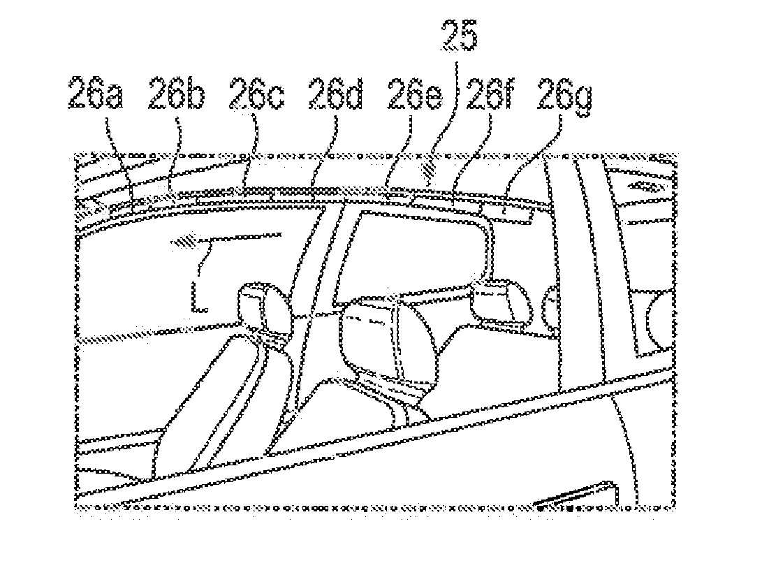
In a method of controlling an interior lighting (25) in a vehicle (18), having a plurality of separately drivable lamps (26a-26g), provision is made that a motion light pattern, in particular a wave light pattern, is generated as a function of vehicle operating data by separately driving the individual lamps (26a-26g), all of the lamps (26a-28g) being driven with an identical or similar light pattern, and the lamps (26a-26g) being driven with the light pattern offset in time. The time offset with which the lamps (26a-26g) are driven is dependent on the driving speed of the vehicle.

Description

RELATED APPLICATIONS[0001]This application corresponds to PCT / EP2013 / 064219, filed Jul. 5, 2013, which claims the benefit of German Application No. 10 2012 013 783.4, filed Jul. 11, 2012, the subject matter, of which are incorporated herein by reference in their entirety.BACKGROUND OF THE INVENTION[0002]The present invention relates to a method of controlling an interior lighting according to the generic part of claim 1. The invention further relates to an interior lighting for a vehicle.[0003]DE 10 2010 018 336 and DE 10 2011 014 262 A1 disclose vehicle interior lightings including a plurality of lamps which can generate a defined light pattern in the vehicle by the lamps being driven separately from each other.[0004]Modern vehicles feature an ever better noise reduction and also better chassis, so that driving noises, for instance wind, rolling or engine noises, are effectively reduced in the vehicle interior. While this increases the driving comfort of the vehicle, it makes it mo...

Claims


Application Information

Patent Timeline
IPC IPC(8): B60Q3/02H05B37/02
CPCB60Q3/0293H05B37/02B60Q3/80B60Q3/16H05B47/10H05B47/105B60Q2900/40B60Q3/00
Inventor BACKES, ULRICH
Owner TRW AUTOMOTIVE ELECTRONICS & COMPONENTS
Learn More