Image forming apparatus with control of transfer and fixing nips

a technology of image forming apparatus and transfer unit, which is applied in the direction of electrographic process apparatus, instruments, optics, etc., can solve the problems of difficult to achieve downsizing and space saving of the apparatus, and achieve the effect of increasing the size of the apparatus and reducing the load generated when the transfer unit is closed

Active Publication Date: 2022-05-31
CANON KK
View PDF9 Cites 0 Cited by
  • Summary
  • Abstract
  • Description
  • Claims
  • Application Information

AI Technical Summary

Benefits of technology

[0006]With the foregoing in view, it is an object of the present invention to provide an image forming apparatus including a transfer unit that is openable and closable to expose the inside of the apparatus and to reduce a load generated when the transfer unit is closed without increasing the size of the apparatus.
[0017]As described above, according to the present invention, in the image forming apparatus including the transfer unit that is openable and closable to expose the inside of the apparatus, the load generated when the transfer unit is closed can be reduced without increasing the size of the apparatus.

Problems solved by technology

This makes it difficult to achieve downsizing and space saving of the apparatus.

Method used


Image

  • Image forming apparatus with control of transfer and fixing nips
  • Image forming apparatus with control of transfer and fixing nips
  • Image forming apparatus with control of transfer and fixing nips

Examples


embodiment 1

[0029]FIG. 8 is a schematic diagram illustrating a configuration of an image forming apparatus 100 according to the present invention. The image forming apparatus illustrated in FIG. 8 is a tandem-type four-color laser beam printer based on an electrophotographic system and uses an intermediate transfer belt 10. Hereinafter, a configuration of the image forming apparatus 100 will be briefly described.

[0030]The image forming apparatus 100 illustrated in FIG. 8 includes drum-shaped electrophotographic photosensitive members (hereinafter, referred to as “photosensitive drums”) 1a to 1d as first image bearing members for respective colors in a main body of the apparatus. The photosensitive drums 1a to 1d are rotatably supported by the image forming apparatus 100 and driven to rotate in an arrow R1 direction by a drive unit (not illustrated). Contact-type charging rollers 2a to 2d and developing devices 4a to 4d are arranged around the photosensitive drums1a to 1d, respectively, along a ...

embodiment 2

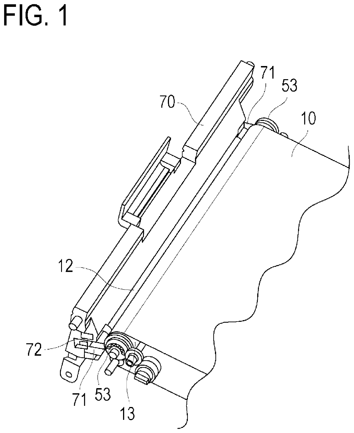
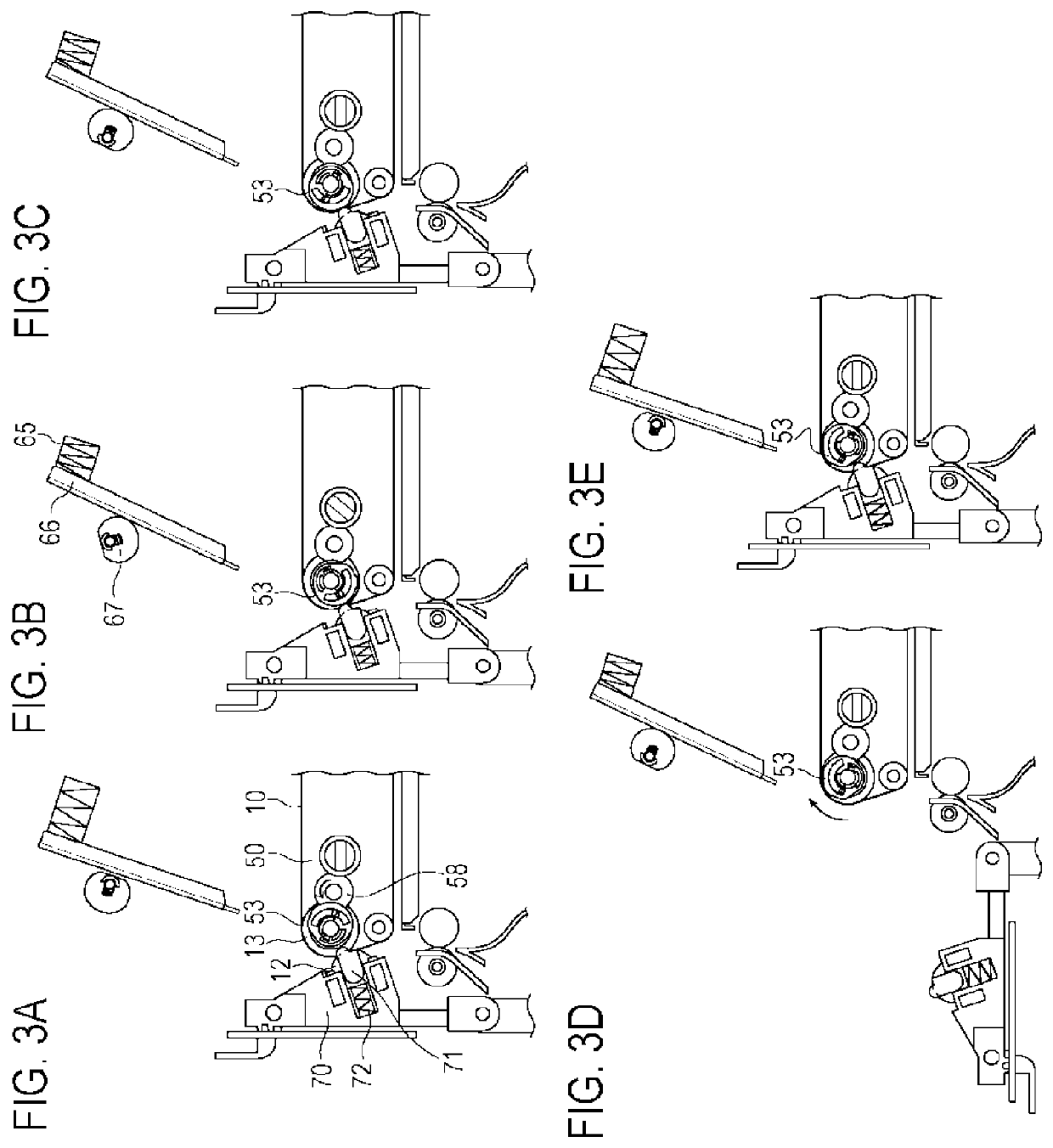
[0065]Next, a configuration specific to Embodiment 2 will be described with reference to FIG. 6. FIG. 6 is a diagram illustrating the vicinity of a transfer roller 91 in an image forming apparatus according to the present invention.

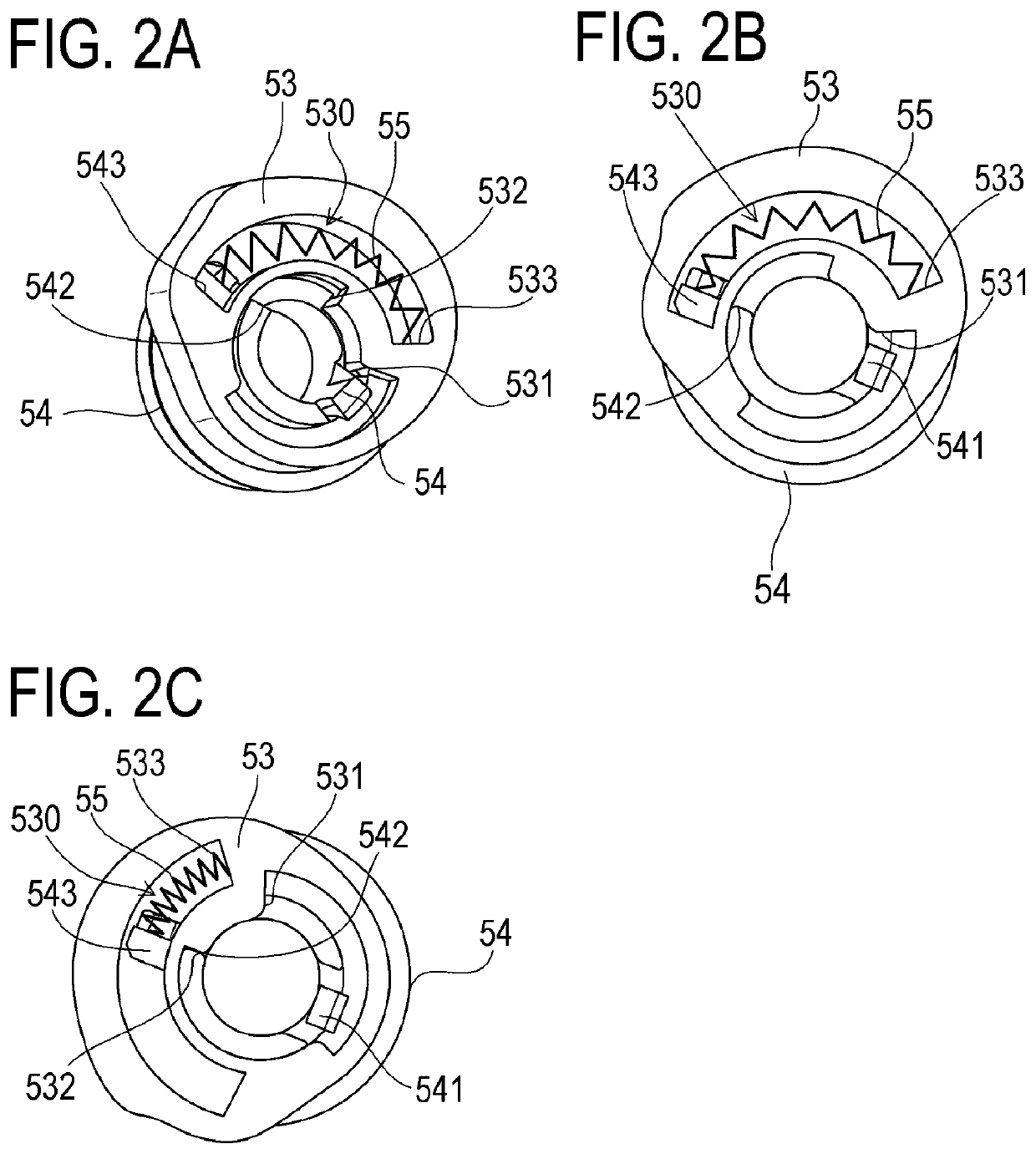
[0066]The image forming apparatus according to the present embodiment is a monochrome printer. A photosensitive drum 1 is disposed at a position opposed to the transfer roller 91 and forms a nip with the transfer roller 91. Separation cams 53 for separating the transfer roller 91 are provided near both ends of the photosensitive drum 1.

[0067]The transfer unit 90 includes the transfer roller 91 and bearings 93, each of which is provided at one end of the transfer roller 91 and has a surface to be in contact with a corresponding one of the separation cams 53 as described in Embodiment 1. One of the bearings 93 at both ends of the transfer roller 91 is provided with a conductive member (not illustrated) for applying a bias to the transfer roller 91. Thus, th...


PUM


Abstract

An image forming apparatus includes a transfer nip control member being movable to a pressing position, where a pressing force for positioning a transfer roller in a transfer nip releasing position is applied to a transfer unit in a closed position, and to a releasing position, where application of the pressing force is released; a fixing nip control mechanism for changing a relative position between a fixing roller and an opposing member to a fixing position, where a fixing nip is formed, and to a fixing nip releasing position; and an interlocking mechanism for moving the transfer nip control member in the releasing position to the pressing position in conjunction with a fixing nip releasing operation by the fixing nip control mechanism. The transfer nip control member in the pressing position is moved to the releasing position when the transfer unit is moved from the closed position to an open position.

Description

BACKGROUND OF THE INVENTIONField of the Invention[0001]The present invention relates to an image forming apparatus, which uses an electrophotographic system or an electrostatic recording system, such as a copying machine, a multifunction machine, and a laser beam printer.Description of the Related Art[0002]There has been conventionally known a configuration of the above image forming apparatus in which a transfer roller serving as a transfer member is abutted against a photosensitive drum serving as an image bearing member, which carries a toner image, via a conveying belt, an intermediate transfer belt, or the like during image formation. When the transfer roller is stored in a state in which the transfer roller is abutted against the photosensitive drum, the conveying belt, the intermediate transfer belt, or the like provided at a position opposed to the transfer roller for an extended period of time, the shape of the transfer belt, the conveying belt, or the intermediate transfer...

Claims


Application Information

Patent Timeline
Patent Type & Authority Patents(United States)
IPC IPC(8): G03G21/16G03G15/00
CPCG03G21/1647G03G15/50G03G21/168G03G21/1638G03G15/1665G03G15/2032G03G21/1685G03G15/1675G03G15/1615G03G15/2035G03G15/1685
Inventor FUKASE, YASUHIROMITSUMATA, AKINORI
Owner CANON KK
Why Eureka
Try Eureka