Optical apparatus

a technology of optical equipment and optical lens, which is applied in the field of optical equipment, can solve the problems of insufficient eye-catching effect as a sales promotion display increase in etc., and achieve the effect of wide visual recognition range, and increasing the size of the apparatus

Active Publication Date: 2019-12-05
FUJIFILM CORP
View PDF0 Cites 0 Cited by
  • Summary
  • Abstract
  • Description
  • Claims
  • Application Information

AI Technical Summary

Benefits of technology

[0023]According to the optical apparatus of the present invention, an aerial image display apparatus that can cause an aerial image to protrude in a forward direction and has a wide visual recognition range of the aerial image can be implemented without increasing the size of the apparatus.
[0024]The aerial image display apparatus implemented by the optical apparatus of the present invention can cause the aerial image to protrude in the forward direction from the beam splitter depending on the distance between the image display unit and the mirror surface by separating the image display unit from the mirror surface. At this point, since the image display unit is installed on the opposite side from the mirror surface and the retroreflective member with respect to the surface of the beam splitter, an increase in size of the apparatus is not accompanied. Furthermore, from the point of view of an observer, the aerial image can be visually recognized in not only the range of view of the retroreflective member but also the range of view of the mirror surface. Thus, the visual recognition range of the aerial image can be significantly increased, compared to that of an aerial image display apparatus in the related art.

Problems solved by technology

According to a review of the present inventors, it is found that the aerial image display apparatus disclosed in JP2012-128454A has an insufficient protrusion distance of the aerial image in the forward direction (direction away) from the mirror unit and has an insufficient eye-catching effect as a sales promotion display.
In addition, while the aerial image can further protrude in the forward direction by installing the display unit away from the mirror, such a case poses a problem in that the size of the apparatus is increased.
In order to increase the protrusion distance, the liquid crystal display device has to be installed away from the beam splitter, and a problem arises in that the size of the apparatus is increased.

Method used


Image

  • Optical apparatus
  • Optical apparatus
  • Optical apparatus

Examples


example 1

[0126]FIG. 19 illustrates a positional relationship among the image display unit 22, the casing 70, and the aerial image B in aerial image display apparatuses 81 to 88 of Examples 1 to 8.

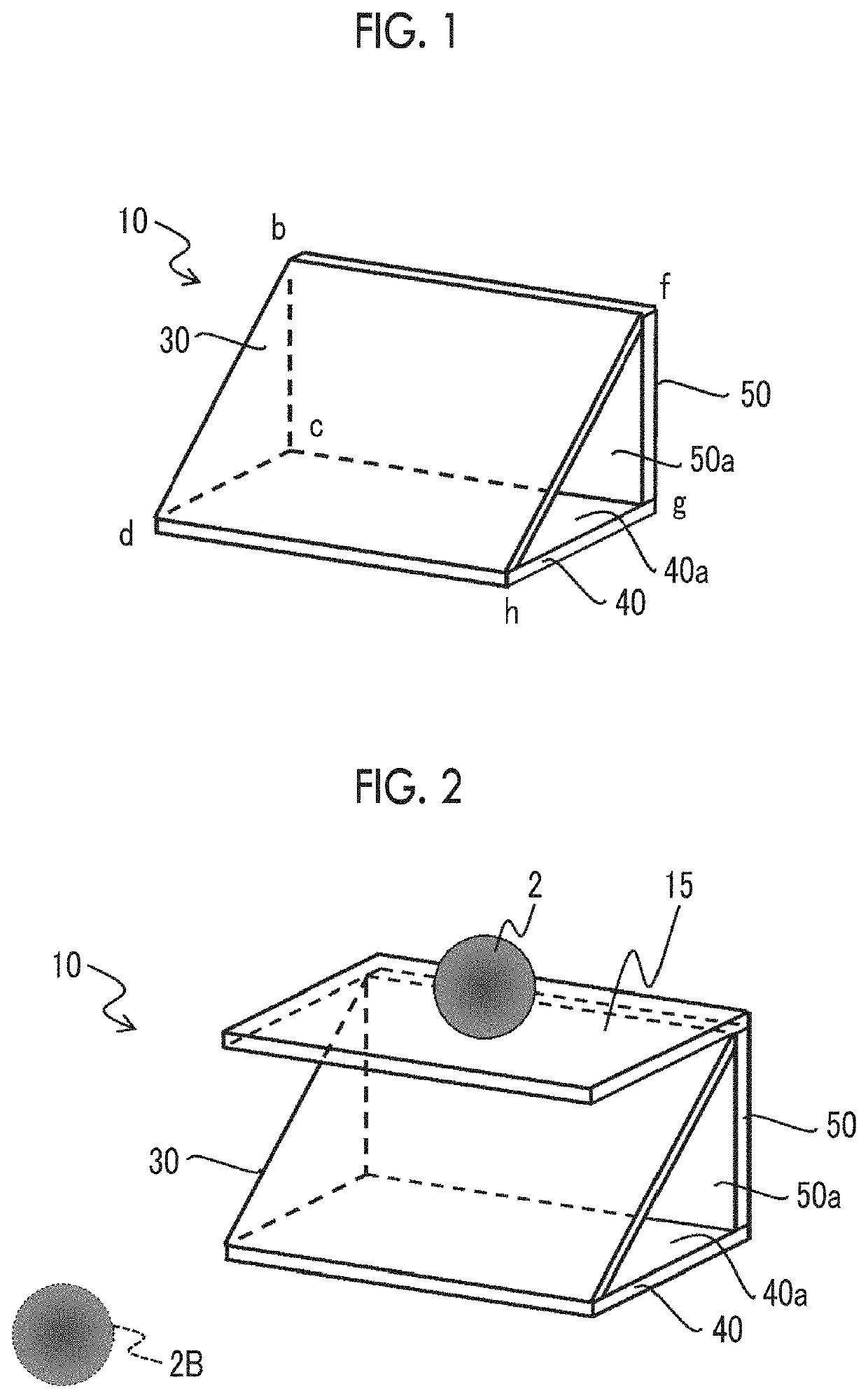
[0127]A bead type retroreflective sheet (product name Scotchlite manufactured by 3M) is bonded to the inner side of the side surface bfgc of the casing 70, and a flat mirror is bonded to the inner side of the bottom surface cghd. In addition, the beam splitter 32 is installed at the position of the plane bfhd.

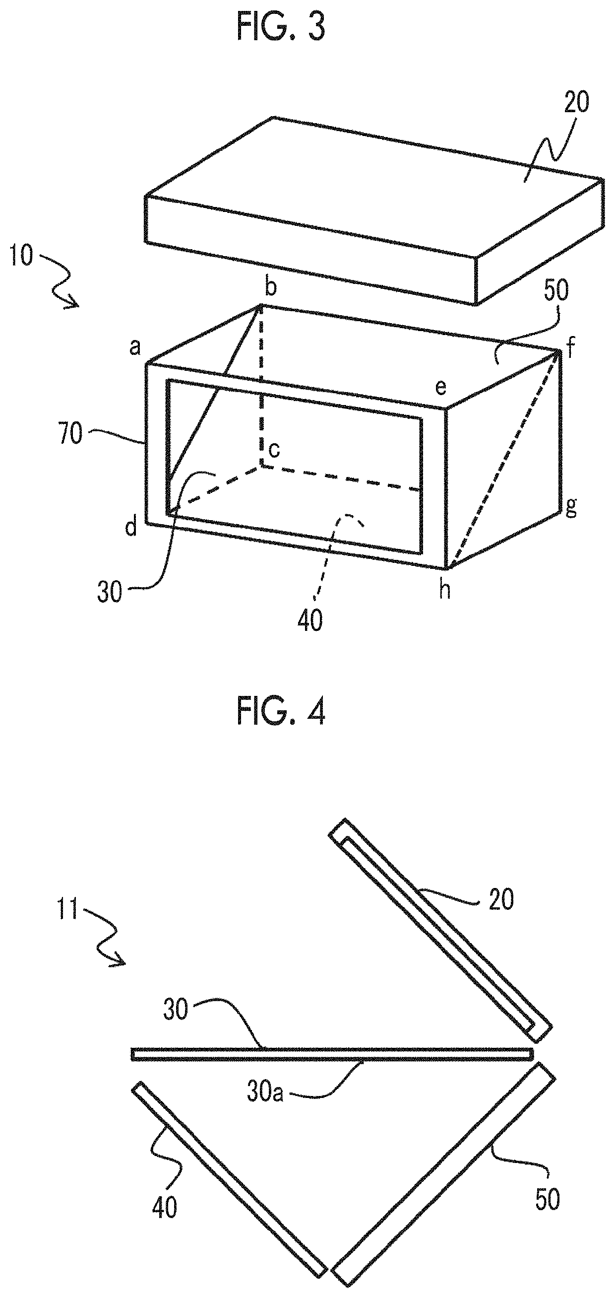
[0128]Furthermore, iPhone (registered trademark) 6s Plus that is a smartphone manufactured by Apple is installed on the upper surface abfe as the image display unit 22. The frame abfe surrounding the open upper surface abfe of the casing 70 corresponds to the installation unit on which the object to be projected is installed. In iPhone (registered trademark) 6s Plus, the emission light is elliptically polarized light and is not linearly polarized light.

[0129]Accordingly, the aerial image displa...

example 2

[0130]In the aerial image display apparatus 81 of Example 1, a corner cube array type retroreflective sheet (product name Nikkalite manufactured by Nippon Carbide Industries Co., Inc) is bonded to the inner side of the side surface bfgc of the casing 70 instead of Scotchlite described above.

[0131]Accordingly, the aerial image display apparatus 82 of Example 2 is manufactured (refer to FIG. 19).

example 3

[0132]In the aerial image display apparatus 82 of Example 2, the retroreflective sheets Nikkalite are bonded to the inner side of a side surface abcd and the inner side of a side surface efgh such that the retroreflective sheets Nikkalite overlap with a triangle bcd and a triangle fgh.

[0133]Accordingly, the aerial image display apparatus 83 of Example 3 is manufactured (refer to FIG. 19).


PUM


Abstract

An optical apparatus includes a beam splitter that transmits a part of an incidence ray and reflects another part of the incidence ray, a mirror member that includes a mirror surface arranged at a position at which light transmitted through the beam splitter is incident, and a retroreflective member that is arranged at a position at which light specularly reflected on the mirror surface, to be incident on the beam splitter and specularly reflected by the beam splitter is incident.

Description

CROSS-REFERENCE TO RELATED APPLICATIONS[0001]This application is a continuation application of International Application No. PCT / JP2018 / 005284, filed Feb. 15, 2018, the disclosure of which is incorporated herein by reference in its entirety. Further, this application claims priority from Japanese Patent Application No. 2017-026213, filed Feb. 15, 2017, the disclosure of which is incorporated herein by reference in its entirety.BACKGROUND OF THE INVENTION1. Field of the Invention[0002]The present invention relates to an optical apparatus for implementing an aerial image display apparatus displaying an image in the air.2. Description of the Related Art[0003]In recent years, an aerial image display apparatus displaying an image in the air where a screen is not present has been suggested and is expected to be used as a sales promotion display having a high eye-catching effect or an input device enabling a touch operation on a video displayed in the air without touching a screen.[0004]Fo...

Claims


Application Information

Patent Timeline
Patent Type & Authority Applications(United States)
IPC IPC(8): G02B27/22G02B27/28G02B5/30G02B5/124
CPCG02B5/124G02B27/2292G02B5/3083G02B27/283G09F9/00G02B30/56
Inventor YAMADA, NAOYOSHIYONEMOTO, TAKASHITOYAMA, HIROFUMISAITOH, YUKITO
Owner FUJIFILM CORP
Why Eureka
Try Eureka