
Sheet post-processing apparatus and image forming apparatus

a post-processing apparatus and image-forming technology, applied in the field of sheet post-processing apparatus, can solve the problems of clogging of staplers, inability to normally perform stapler binding operations, so as to achieve the effect of not increasing the size of the apparatus

Active Publication Date: 2018-05-03
COPYER
View PDF2 Cites 0 Cited by
  • Summary
  • Abstract
  • Description
  • Claims
  • Application Information

AI Technical Summary

Benefits of technology

The present invention provides a sheet post-processing apparatus that can protect the stapler and sheet material while performing a sheet-binding process without increasing the size of the apparatus. Additionally, an image forming apparatus including an image forming unit, binding unit, and regulating unit is provided to prevent sheets from being inserted when the binding unit performs a setting operation for a binding member. Overall, the invention offers an optimal solution for safeguarding the stapling unit and sheet bundle during post-processing settings.

Problems solved by technology

When the binding process is performed on the sheet bundle by the stapler, a problem called jam, in which the staple is clogged at a portion in a stapler mechanism without being normally driven, may occur.
Under such a state, the binding operation by the stapler cannot normally be performed.
Also when all the staples loaded to the cartridge of the stapler are used, the binding operation by the stapler cannot normally be performed.
The bite of the foreign matters may lead to a failure of the stapler.
Further, when the sheet bundle is inserted from the opening portion at a timing when the stapler performs the setting operation, the sheet bundle may be flawed or damaged.
However, the configuration leads to an increase in size of the apparatus to increase costs.

Method used


Image

  • Sheet post-processing apparatus and image forming apparatus
  • Sheet post-processing apparatus and image forming apparatus
  • Sheet post-processing apparatus and image forming apparatus

Examples


Embodiment Construction

[0038]Now, embodiments of the present invention are described with reference to the accompanying drawings.

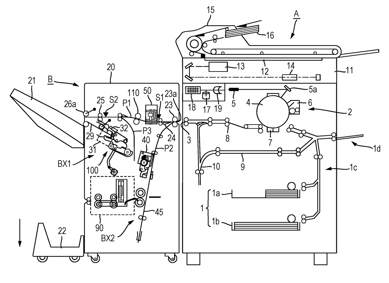
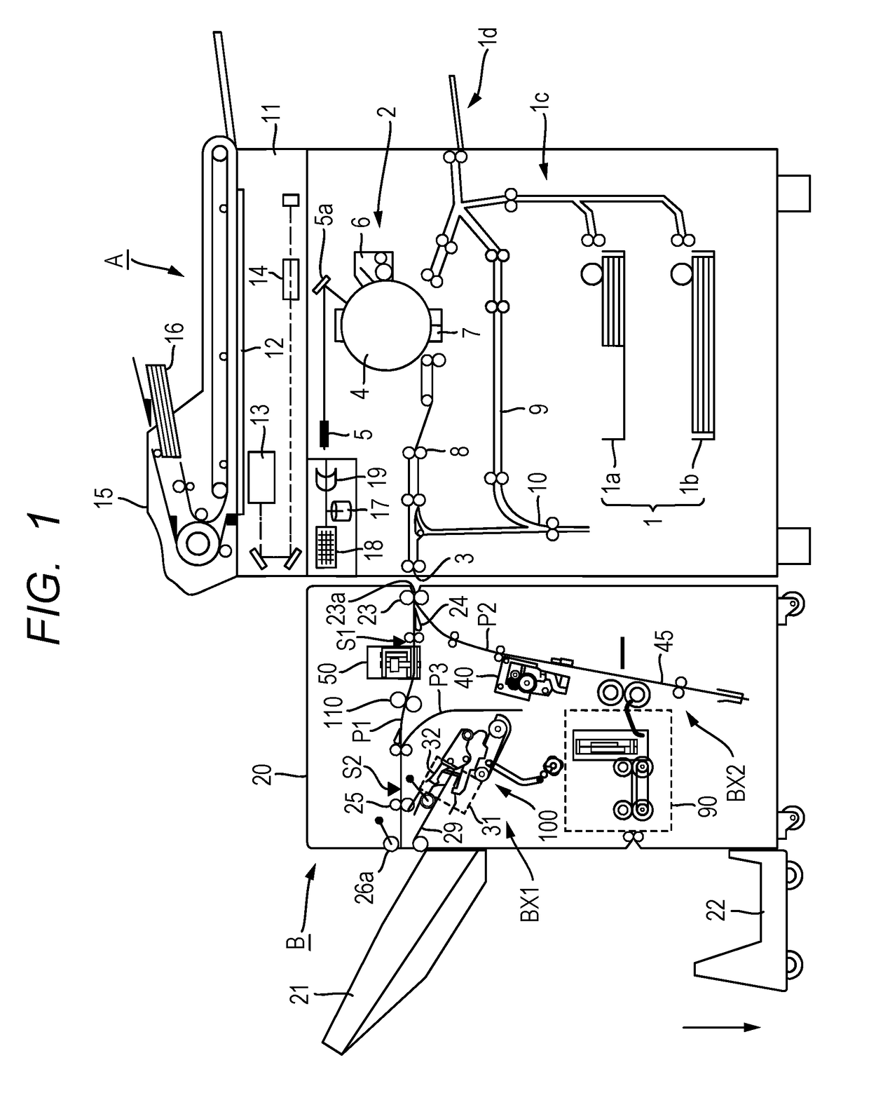
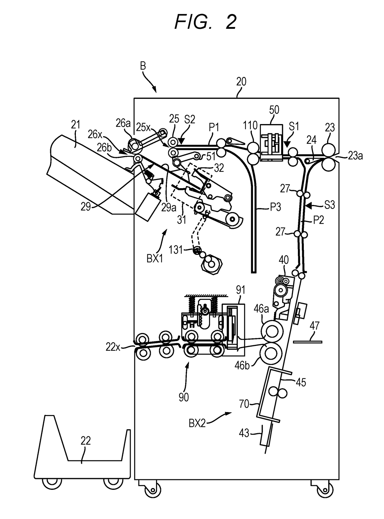
[0039]FIG. 1 illustrates an overall structure of an image forming system including a sheet post-processing apparatus B and an image forming apparatus A to be used together with the sheet post-processing apparatus B. The image forming system in FIG. 1 includes the image forming apparatus A and the sheet post-processing apparatus B. FIGS. 2 to 13 more specifically illustrate structures and operations of main parts of the sheet post-processing apparatus B to be used together with the image forming apparatus A in FIG. 1.

[0040]As illustrated in FIG. 1, the image forming system according to this embodiment includes the image forming apparatus A and the sheet post-processing apparatus B (an abbreviation “processing apparatus B” is also used hereinafter). In the image forming system according to this embodiment, a sheet feed and delivery path has construction in which a delivery port 3 ...


PUM


Abstract

Provided is a sheet post-processing apparatus capable of reliably protecting an edge-binding stapling unit and a sheet material, and of performing a sheet-binding process without increasing the size of the apparatus. The sheet post-processing apparatus includes: a binding unit movable to a binding position in which the binding unit performs a binding process using a binding member on a sheet, and an access position in which a user is accessable to the binding unit; and a control unit configured to cause, when the binding unit performs a setting operation for the binding member, the binding unit to perform the setting operation after causing the binding unit to move to a position different from the access position.

Description

BACKGROUND OF THE INVENTIONField of the Invention[0001]The present invention relates to a sheet post-processing apparatus, which is configured to perform a binding process for a sheet using a binding unit including a binding portion configured to drive a binding member through the sheet and bend the binding member, and to an image forming apparatus including the sheet post-processing apparatus.Description of the Related Art[0002]Hitherto, there is known a configuration in which a sheet post-processing apparatus is arranged in a post-stage of an image forming apparatus, which is configured to form an image using various types of image forming methods, to thereby perform a folding process or a bookbinding process. In particular, the sheet post-processing apparatus configured to perform the bookbinding process includes, for example, a stapler serving as a binding unit, and is configured to perform the bookbinding by stacking sheets conveyed from the image forming apparatus and binding ...

Claims


Application Information

Patent Timeline
Patent Type & Authority Applications(United States)
IPC IPC(8): B65H37/04G06K15/16B65H43/00B65H39/16B42B4/00G03G15/00B65H31/30B65H31/36B65H31/02
CPCG06K15/16B65H43/00B65H37/04B65H39/16B42B4/00B65H2801/27B65H2405/113B65H2301/4212G03G15/6544B65H2301/4213G03G2215/00831G03G2215/00818B65H2403/942B65H31/3027G03G2215/00827B65H31/36B65H31/02B65H2601/26B65H2511/528B65H2408/122B65H2220/01
Inventor OKAMOTO, KOJI
Owner COPYER
Learn More