Image pickup apparatus that has connector for external device, disposed at optimum location

a pickup apparatus and connector technology, applied in the field of image pickup apparatus, can solve the problems of increasing the total height of the image pickup apparatus as a manufactured product, affecting the user's photographing operation, and increasing the size of the image pickup apparatus, so as to achieve the effect of not increasing the size of the apparatus

Active Publication Date: 2020-04-14
CANON KK
View PDF15 Cites 0 Cited by
  • Summary
  • Abstract
  • Description
  • Claims
  • Application Information

AI Technical Summary

Benefits of technology

[0005]The present invention provides an image pickup apparatus that includes a display unit provided at a front end of a handle and capable of being opened to both of horizontal right and left sides and is capable of having a connector for an external device, such as an external microphone, disposed at an optimum location without increasing the size of the apparatus.
[0007]According to the present invention, in the image pickup apparatus that includes a display unit provided at a front end of a handle and capable of being opened to both of horizontal right and left sides, it is possible to dispose a connector for an external device, such as an external microphone, at an optimum location without increasing the size of the apparatus.

Problems solved by technology

However, there is a problem that a cable of the connected external microphone can hinder the user from performing photographing operation.
If the technique described in Japanese Laid-Open Patent Publication (Kokai) No. 2001-189883 is applied to the image pickup apparatus of this type, there arises a problem that the front end of the handle becomes very thick, which increases the total height of the image pickup apparatus as a manufactured product, resulting in an increased size thereof.

Method used


Image

  • Image pickup apparatus that has connector for external device, disposed at optimum location
  • Image pickup apparatus that has connector for external device, disposed at optimum location
  • Image pickup apparatus that has connector for external device, disposed at optimum location

Examples


Embodiment Construction

[0042]The present invention will now be described in detail below with reference to the accompanying drawings showing embodiments thereof.

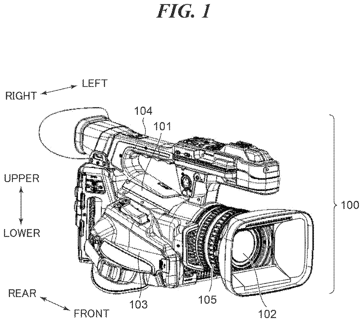
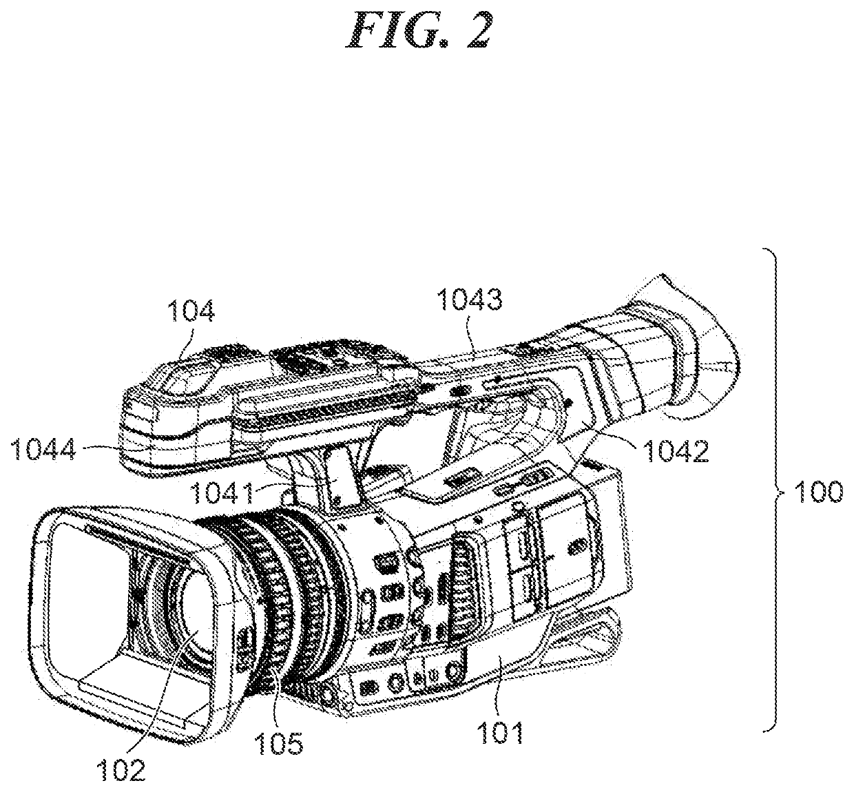
[0043]FIG. 1 is a perspective view of a digital video camera as an image pickup apparatus according to an embodiment of the present invention, as viewed from the front right side. FIG. 2 is a perspective view of the digital video camera shown in FIG. 1, as viewed from the front left side. Note that in the present embodiment, as shown in FIG. 1, a side of the digital video camera toward an object is referred to as the front side, and a right side and a left side, as viewed from a rear side of the digital video camera, are referred to as the right side and the left side.

[0044]As shown in FIGS. 1 and 2, the digital video camera, denoted by reference numeral 100 (hereinafter referred to as the camera 100), according to the present embodiment includes a camera body 101, an image pickup optical system 102, a grip part 103, a handle 104, and operation ri...


PUM


Abstract

An image pickup apparatus capable of having an external device connector disposed at an optimum location without increasing the size of the apparatus. The image pickup apparatus includes an apparatus body, a handle that includes a front leg part and a rear leg part, which extend upward from the apparatus body, and a gripping part which connects between the front leg part and the rear leg part substantially in parallel with an optical axis of an image pickup optical system, a front part that is integrally formed with the handle on a front side of the handle, and a display unit that is supported in a manner rotatable with respect to the front part in a substantially horizontal direction via a first rotational shaft portion. A connector to which a first external device is connected is arranged on a side surface of the front leg part.

Description

BACKGROUND OF THE INVENTIONField of the Invention[0001]The present invention relates to an image pickup apparatus, such as a digital camera and a digital video camera.Description of the Related Art[0002]In recent years, for an image pickup apparatus, such as a digital video camera, there have been proposed an increasing number of models each equipped with a connector for connecting an external microphone thereto, with a view to enabling the use of a higher performance external microphone than a built-in microphone. However, there is a problem that a cable of the connected external microphone can hinder the user from performing photographing operation.[0003]To solve this problem, in Japanese Laid-Open Patent Publication (Kokai) No. 2001-189883, there has been proposed a technique for arranging a connector for an external microphone on one of side surfaces of a supporting portion provided on an image pickup apparatus such that the supporting portion protrudes forward from a front end ...

Claims


Application Information

Patent Timeline
Patent Type & Authority Patents(United States)
IPC IPC(8): H04N5/225G03B31/00G03B17/56
CPCG03B31/00H04N5/225251G03B17/563H04N23/50G03B17/02H04N23/531
Inventor YAMAGATA, KENJITERUYA, YUKO
Owner CANON KK
Why Eureka
Try Eureka