Mechanical connection for a MEMS and NEMS device for measuring a variation in pressure, and device comprising such a mechanical connection

a mechanical connection and pressure variation technology, applied in the field of microphones, can solve the problems of affecting the quality of the signal before any transduction, and increasing the density and size of the holes, so as to avoid the deformation of the mobile electrode (or of the mobile electrode) and the structure, and not reducing the capacitive detection capacity

Active Publication Date: 2022-05-17
COMMISSARIAT A LENERGIE ATOMIQUE ET AUX ENERGIES ALTERNATIVES
View PDF13 Cites 4 Cited by
  • Summary
  • Abstract
  • Description
  • Claims
  • Application Information

AI Technical Summary

Benefits of technology

[0025]In particular it seeks to provide a MEMS and / or NEMS device for measuring a variation in pressure, for example a capacitive detection MEMS and / or NEMS microphone, which makes it possible to avoid the disadvantages due to the presence of a backplate electrode, while at the same time avoiding deformation of the mobile electrode (or of the mobile electrodes) and of the structure of the device, and to do so while not reducing the capacitive detection capacity, or even while at the same time increasing the capacitive detection capacity.
[0048]According to one embodiment, the detection means comprise a mobile electrode connected to the third connection or to the transmission component and at least one fixed electrode, the electrodes extending in the main plane and the airgap between the mobile electrode and the at least one fixed electrode being defined by a dimension of the electrodes in the main plane and by the thickness of the electrodes, the translational motion transmitted by the third connection to the mobile electrode being able to cause the airgap between the mobile electrode and the at least one fixed electrode to vary in the direction of translation. That allows the creation of capacitive transduction with a variation in airgap.
[0050]According to one alternative embodiment, the detection means comprise a mobile electrode connected to the third connection or to the transmission component and at least one fixed electrode, the electrodes extending in the main plane and the mutually-facing surface areas of the mobile electrode and of the at least one fixed electrode being defined by a dimension of the electrodes in the main plane and by the thickness of the electrodes, the translational motion transmitted by the third connection to the mobile electrode being able to cause the mutually-facing surface areas of the mobile electrode and of the at least one fixed electrode to vary in the direction of translation. That allows the creation of capacitive transduction with a variation of surface area.

Problems solved by technology

This structure offers a certain number of advantages, although it does have disadvantages notably on account of the presence of the backplate electrode.
Thus, when the holes are too small and / or too widely spaced, the acoustic resistance results in a noise (induced by the backplate electrode) which impairs the quality of the signal before any transduction.
In order to limit this resistance, the density and size of the holes may be increased, but this has the direct consequence of reducing the mutually-facing areas, which proportionately reduces the capacitive detection.
Thus, the electrical signal is weaker and the electronic noise (notably that induced by the signal processing) is less well masked.
In both instances, that leads to an impairment in the detection threshold.
Because the backplate electrode is the main cause of performance losses, one solution is to reduce its impact or even to eliminate it.
However, in the case of piezoelectric detection, the number of charges is given by the mechanical stresses within the material, it cannot be increased by a polarizing voltage or any other external artefact.
This is because, aside from the fact that this has the effect of increasing the size of the structure and therefore the cost thereof, a diaphragm with a larger surface area will displace more air as it deforms.
Therefore, a piezoelectric detection microphone offers a limited improvement compared with capacitive detection.
A first problem associated with this configuration is the deformation of the mobile electrode under the effect of the electrostatic forces, which limits the length of the lever arm.
This problem is amplified when the substrate is not conducting and only a single backplate electrode is used, because the electrostatic forces in this case cannot balance each other out locally (they can be balanced out by creating a Roberval balance, but they cannot be cancelled out locally).
However, the thickness of the MEMS layer is limited to 10-30 μm by epitaxy and exceeding that would render the method overly expensive.
Furthermore, if the thickness were increased, the deep etching would require wide trenches in order to conform to a reasonable width / depth aspect ratio, and this could lead to excessive losses around the diaphragm or the piston.
A second problem stems from the thickness of the thin layer (NEMS) of the diaphragm or of the piston.
Furthermore, in order to polarize each of the backplate electrodes delimited by this network, it is necessary to create polarization blocks, and this takes a not-insignificant amount of space.
If the number of stiffening beams and therefore the number of backplate electrode blocks is reduced, the first problem of the deformation of the mobile electrode under the effect of the electrostatic forces is again encountered.
A third problem stems from the fact that the capacitive detection airgap is defined and therefore limited by the thicknesses of the two sacrificial (oxide) layers which allow the mobile electrode to be freed from the backplate electrode (or backplate electrodes).
As with the previous problems, the fact that these thicknesses are the same over the entire structure dictates compromises.
Now, limiting the length of the lever arm also limits the size of the capacitive detection in the direction of the arm, especially when the capacitive density may have already been reduced if stiffening beams and polarizing blocks are added.
Furthermore, this configuration imposes limits on the airgap and therefore on the capacitive density.

Method used


Image

  • Mechanical connection for a MEMS and NEMS device for measuring a variation in pressure, and device comprising such a mechanical connection
  • Mechanical connection for a MEMS and NEMS device for measuring a variation in pressure, and device comprising such a mechanical connection
  • Mechanical connection for a MEMS and NEMS device for measuring a variation in pressure, and device comprising such a mechanical connection

Examples


first embodiment

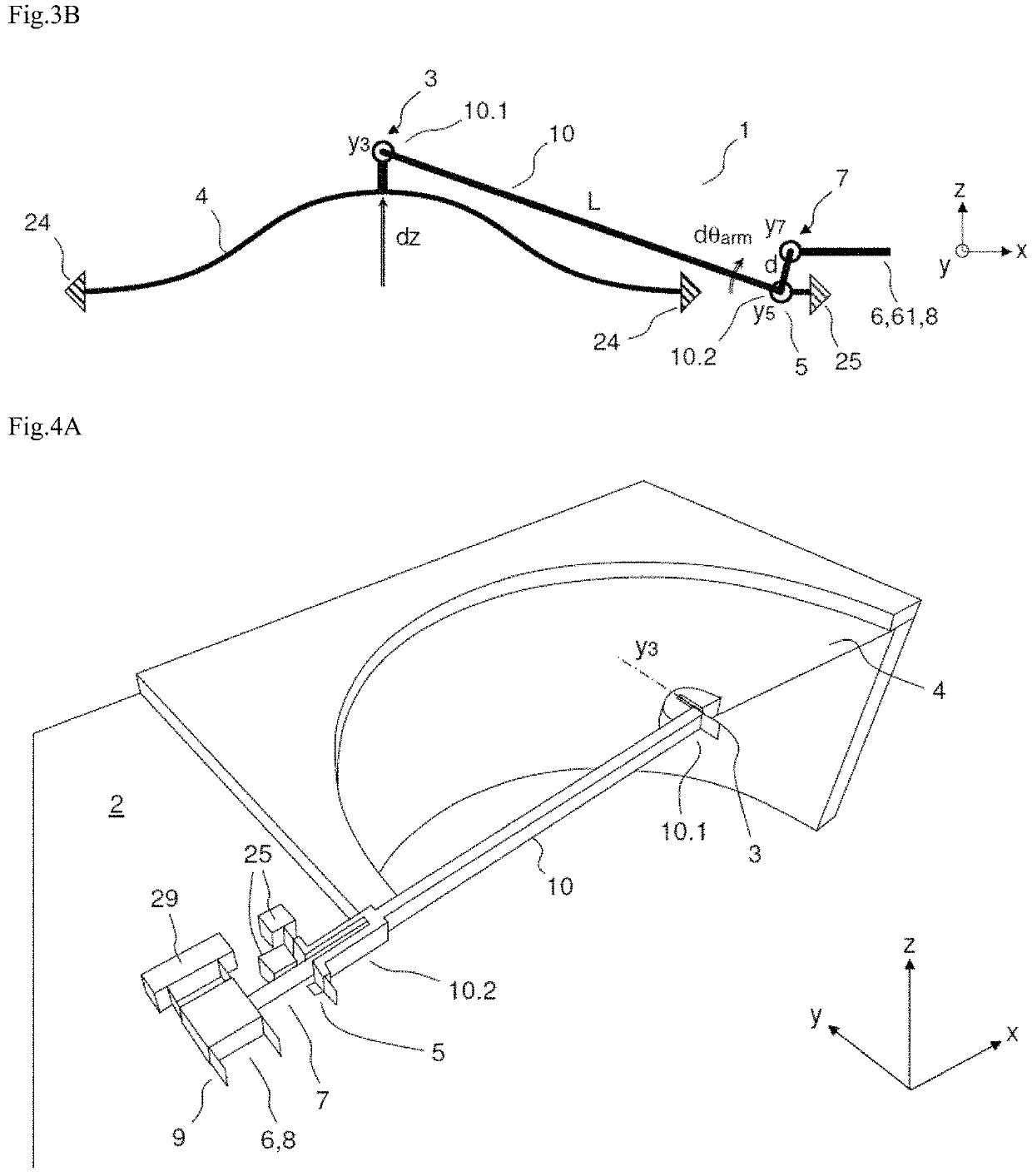
[0087]FIGS. 4A to 4D depict various views of a MEMS-NEMS device for measuring variation in pressure according to a It might be a microphone or an absolute-pressure or differential-pressure sensor. For better legibility, certain parts, such as the anchoring blocks for example, are depicted in only half a plane. Furthermore, the grey arrows indicate the directions of coupling of the connections and the white arrows indicate the flexible directions of the connections.

[0088]In FIGS. 4A to 4D, the motion detection means 6 (for example capacitive detection means) are not depicted in detail but indicated schematically by a detection block. Even though only a certain one (or plurality) of the elements make up the detection block is mobile, namely deformable or able to be moved, it will be stated for the sake of simplification that the translational motion is transmitted to the detection block: that must therefore be understood as meaning that the translational motion is transmitted only to...

second embodiment

[0120]Detection by variation in airgap is well suited to small movements because it provides a greater variation in capacitance for a given movement. However, for large movements, it becomes nonlinear and detection by variation in surface area according to this second embodiment is then more suitable. Furthermore, when the electrode is not placed in a vacuum, the variation in airgap will be accompanied by an effect known as “squeeze film damping” which corresponds to the squeezing of the film of air between two electrodes. This phenomenon leads to a damping effect, and therefore to noise. A variation in surface area creates less mechanical noise. Finally, the nonlinear effect of the variation in airgap, firstly, can be used to obtain a negative stiffness dependent on the bias voltage, and thus to regulate the resonant frequency of the device.

[0121]Both variants of capacitive-detection block can be implemented in a MEMS-NEMS device for measuring variation in pressure according to the...

third embodiment

[0133]As an alternative to capacitive transduction, the detection block 6 may comprise a resonant beam, so as to perform detection using resonance. This alternative applies to all the embodiments, and more broadly to any MEMS-NEMS device for measuring the variation in pressure according to the invention. However, it is advantageous to perform detection by resonance in a cavity at a reduced pressure, namely for example according to the second or third embodiment described later. This is because in order to obtain a good Q factor, the viscous damping of a resonator needs to be reduced by siting it in a rarefied atmosphere.

[0134]The detection block may then comprise a resonant beam advantageously placed in a reduced-pressure cavity, the motion of the diaphragm or of the piston being converted by virtue of the mechanical connection of the invention into an in-plane translational motion which is transmitted to the resonant beam which can thus be compressed or tensioned in the plane. The ...


PUM

PropertyMeasurementUnit
thicknessaaaaaaaaaa
thicknessaaaaaaaaaa
torsion angleaaaaaaaaaa

Abstract

A mechanical connection is provided for a microelectromechanical and / or nanoelectromechanical device for measuring a variation in pressure. The device includes a fixed component extending in a main plane, a mobile component to move or deform in an out-of-plane direction under effect of a variation in pressure, and a detector of movement or deformation having at least one mobile element. The mechanical connection includes: a lever arm; a first connection connecting the mobile component to a first end of the lever arm, the first connection transmitting out-of-plane movement of the mobile component to the first end of the lever arm while allowing out-of-plane rotation of the lever arm about a direction of rotation; a second connection connected to the second end of the lever arm to allow mainly an out-of-plane rotation of the lever arm about an axis of rotation extending in the direction of rotation; a third connection connecting the lever arm to the detector at a given distance from the axis of rotation in the out-of-plane direction, the third connection being designed to convert the rotation of the lever arm about the axis of rotation into a translation in the plane of the at least one mobile element in a direction of translation.

Description

CROSS-REFERENCE TO RELATED APPLICATIONS[0001]This application claims priority to foreign French patent application No. FR 1908128, filed on Jul. 18, 2019, the disclosure of which is incorporated by reference in its entirety.FIELD OF THE INVENTION[0002]The present invention falls within the field of microphones and more generally of devices for measuring a variation in pressure using “MEMS” (MicroElectroMechanical Systems) and / or “NEMS” (NanoElectroMechanical Systems) technology. Devices employing these two technologies will be referred to throughout the description as “MEMS-NEMS devices”.[0003]More specifically, the invention relates to a mechanical connection for a MEMS-NEMS device for measuring the variation in pressure which employs the detection of motion (movement or deformation) of a mobile component such as a diaphragm or a piston with respect to a fixed component such as a substrate, the motion being transmitted to a motion detector, notably a capacitive detector, which allo...

Claims


Application Information

Patent Timeline
Patent Type & Authority Patents(United States)
IPC IPC(8): H04R29/00H04R17/02H04R19/04H01L41/08H01H1/00G05G11/00G01L9/00B81B3/00F16C11/04
CPCH04R29/004H04R17/02H04R19/04B81B3/0051B81B2201/032B81B2201/037B81B2203/051F16C11/04G01L9/001G01L9/0072G05G11/00H01H1/0036H01H2001/0078H01L41/08H04R2201/003G01L9/0073G01L9/0042G01L9/0054G01L9/0089B81B5/00B82Y40/00B81B2201/0257B81B2203/0127B81B2201/0264B81B2203/04B81B2203/06H10N30/00
Inventor JOET, LOÏC
Owner COMMISSARIAT A LENERGIE ATOMIQUE ET AUX ENERGIES ALTERNATIVES
Why Eureka
Try Eureka