
Method for improved startup of an air separation unit having a falling film vaporizer

a technology of falling film vaporizer and air separation unit, which is applied in the direction of cold treatment separation, solidification, liquefaction, etc., can solve the problems of plant trip, significant delay in startup, and difficulty in hydraulically transferring liquids of the main condenser-reboiler, so as to reduce the flow rate of liquid oxygen product and reduce the effect of liquid oxygen product flow ra

Active Publication Date: 2022-05-03
LAIR LIQUIDE SA POUR LETUDE & LEXPLOITATION DES PROCEDES GEORGES CLAUDE
View PDF4 Cites 0 Cited by
  • Summary
  • Abstract
  • Description
  • Claims
  • Application Information

AI Technical Summary

Benefits of technology

The patent describes an improved method for starting a process by stopping the flow of liquid to the closed core of a heat exchanger and reducing the heat exchange area, which increases the ΔT and ΔP in the condenser / reboiler. This method also reduces dry vaporization of the open core and speeds up the recovery of oxygen purity. Additionally, the method includes steps of introducing a cooled and compressed air stream into the higher pressure column and withdrawing an oxygen-enriched liquid stream from the bottom section of the higher-pressure column. The result is an improved startup process for the process.

Problems solved by technology

However, an ASU with a falling film main condenser-reboiler often suffers a drawback of having difficulty of hydraulically transferring the liquids (refluxes) from the higher pressure column to the lower pressure column during plant startup.
When the pressure differential between the two columns is not sufficient to overcome the hydraulics created by the difference in elevation in a stacked column configuration, liquid sent from the bottom of the higher pressure column to the upper section of the lower pressure column will suddenly quit flowing, which interrupts the startup process and can lead to a plant trip.
This often causes a significant delay in startup, and consequently, economic impact.

Method used


Image

  • Method for improved startup of an air separation unit having a falling film vaporizer

Examples


Embodiment Construction

[0025]While the invention will be described in connection with several embodiments, it will be understood that it is not intended to limit the invention to those embodiments. On the contrary, it is intended to cover all the alternatives, modifications and equivalence as may be included within the spirit and scope of the invention defined by the appended claims.

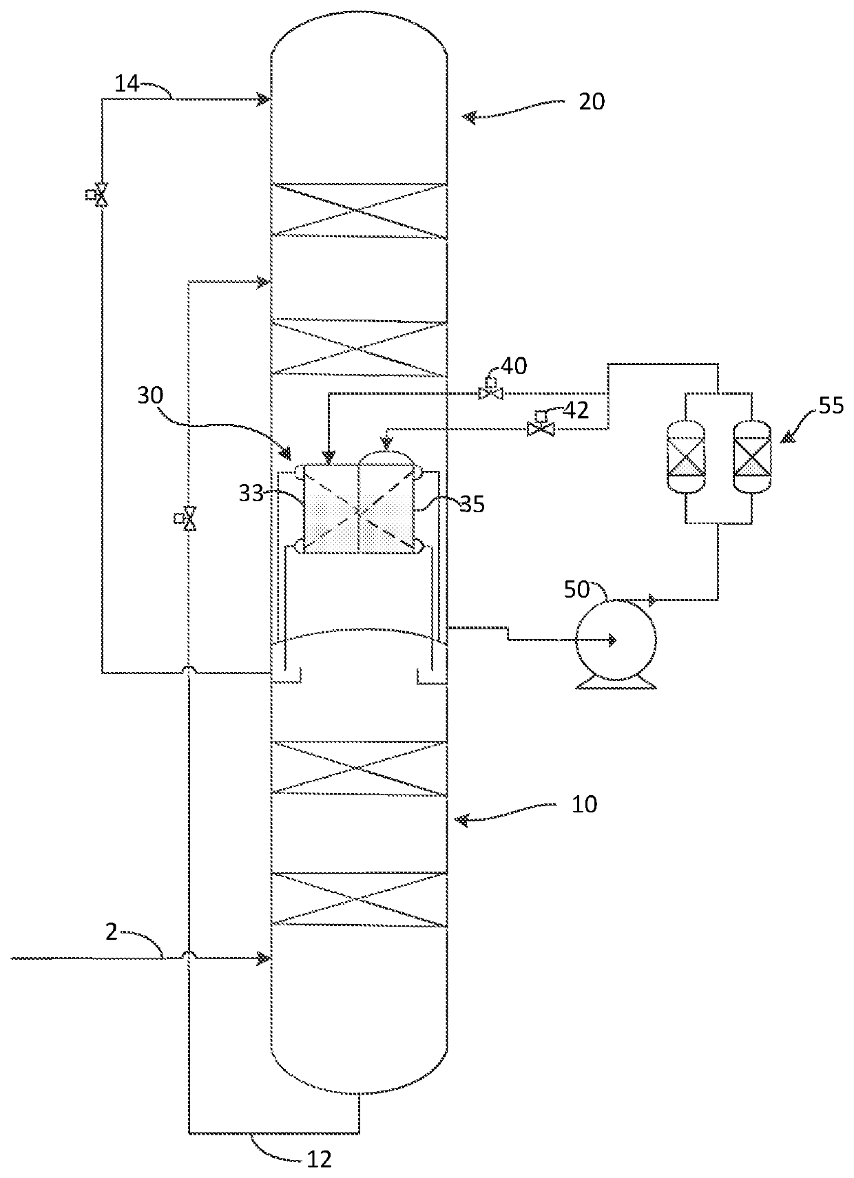
[0026]Now turning to the FIGURE. Air 2, which has previously been compressed, purified, and cooled in a main heat exchanger is introduced into at least the higher pressure column 10. Oxygen enriched stream 12 is withdrawn from a lower portion of higher pressure column 10 and sent to an intermediate section of lower pressure column 20 for further separation. A liquid nitrogen stream 14, which is formed by nitrogen enriched vapors condensing in falling film vaporizer 30, is withdrawn from an upper portion of higher pressure column 10 and sent to an upper portion of lower pressure column 20 to act as a reflux stream.

[0027]Within ...


PUM


Abstract

A method for starting up an air separation plant having a higher-pressure column, a lower-pressure column, and a falling film vaporizer disposed within a lower section of the lower-pressure column is provided. The method can include the steps of: introducing a cooled and compressed air stream into the higher pressure column; withdrawing an oxygen-enriched liquid stream from a bottom section of the higher-pressure column and introducing said oxygen-enriched liquid stream to an upper section of the lower-pressure column; and exchanging heat between nitrogen gas coming from a top section of the higher-pressure column and liquid oxygen from the lower-pressure column within the falling film vaporizer. During a start-up period, flow of liquid oxygen is at least reduced to the closed core. This reduces the available heat exchange area during start up, which increases ΔT and ΔP in the condenser / reboiler.

Description

TECHNICAL FIELD OF THE INVENTION[0001]The present invention generally relates to a method and apparatus for efficiently starting up an air separation plant that uses a falling film (down flow) type vaporizer.BACKGROUND OF THE INVENTION[0002]Air separation plants separate atmospheric air into its primary constituents: nitrogen and oxygen, and occasionally argon, xenon and krypton. These gases are sometimes referred to as air gases.[0003]A typical cryogenic air separation process can include the following steps: (1) filtering the air in order to remove large particulates that might damage the main air compressor; (2) compressing the pre-filtered air in the main air compressor and using interstage cooling to condense some of the water out of the compressed air; (3) passing the compressed air stream through a front-end-purification unit to remove residual water and carbon dioxide; (4) cooling the purified air in a heat exchanger by indirect heat exchange against process streams from the...

Claims


Application Information

Patent Timeline
Patent Type & Authority Patents(United States)
IPC IPC(8): F25J3/02F25J3/04
CPCF25J3/04412F25J3/0409F25J3/04393F25J3/04406F25J3/04478F25J3/04818F25J3/04848F25J2280/10F25J2250/04F25J2245/50F25J2235/50F25J2205/60F25J3/0486
Inventor KONG, PAUL
Owner LAIR LIQUIDE SA POUR LETUDE & LEXPLOITATION DES PROCEDES GEORGES CLAUDE
Learn More