
Diesel exhaust particulate collectors

a technology for collecting equipment and diesel exhaust, which is applied in the direction of exhaust treatment electric control, separation process, filtration separation, etc., can solve the problems of reducing the efficiency of the engine, accumulating and building up to the point of restricting the flow, and affecting the effect of cleaning the filter

Active Publication Date: 2022-04-05
FSX EQUIP
View PDF29 Cites 0 Cited by
  • Summary
  • Abstract
  • Description
  • Claims
  • Application Information

AI Technical Summary

Benefits of technology

The system efficiently removes particulates from diesel particulate filters and oxidation catalysts, providing a rapid and economical turnaround by utilizing alternating air and liquid pressures to dislodge and collect soot and ash, while ensuring filter integrity and safety.

Problems solved by technology

Due to the high pressures and temperatures of the exhaust systems the particulate material is driven hard against the “dirty” side of the filter, where it eventually accumulates and builds up to the point of restricting the flow and reducing efficiency of the engine.
DPFs consequently require periodic cleaning to remove the accumulated matter and return them to service, since due to their very substantial cost they are not normally considered disposable items.
Since much of the accumulated material adheres tenaciously to the filter medium, effectively cleaning the filters tends to be quite challenging.
Jets of high pressure air have commonly been used, but while reasonably effective in many instances, the ability of air to remove the particulates is ultimately limited by the compressibility of air as a gas, and other factors.
Water and other liquids have also been used, but the resistance offered by a filter medium originally designed for use with a gas rather than liquids presents difficulties, when trying to force the liquid through the medium with a pressure and flow that is to remove the deposits.
In particular, the permissible pressure differential when using water or another liquid is severely limited, due to the potential for fracturing / rupturing the cellular walls and destroying the filter, with the result that much of the particulate is not removed.
Therefore, while both pressurized air / gas and water / liquid have previously been employed to clean DPFs, the ability of available systems to effectively remove particulate has often been significantly limited by factors such as those discussed above.

Method used


Image

  • Diesel exhaust particulate collectors
  • Diesel exhaust particulate collectors
  • Diesel exhaust particulate collectors

Examples


Embodiment Construction

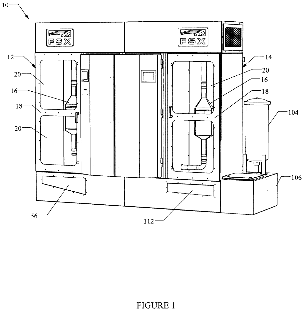
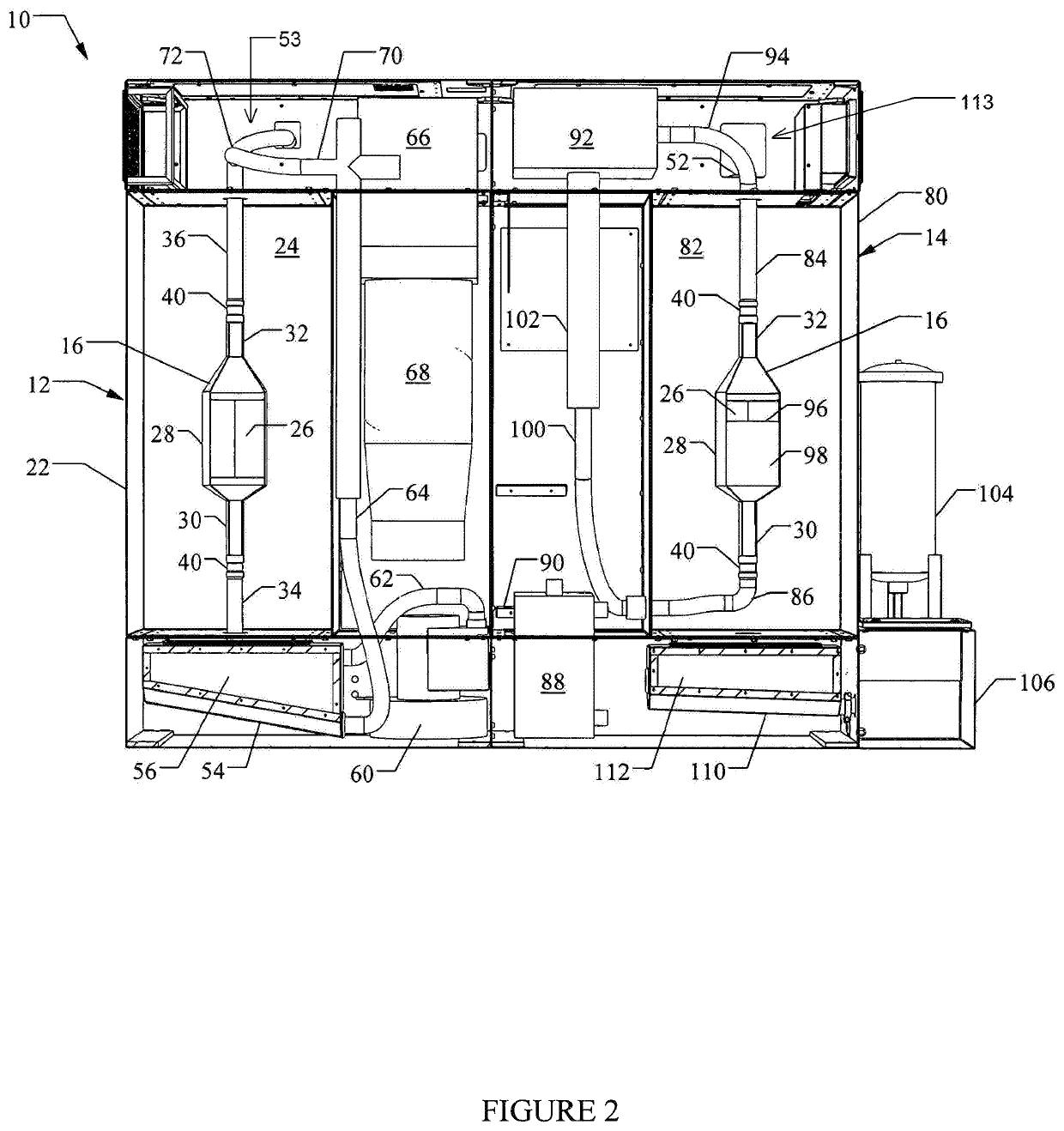
[0029]FIG. 1 shows a filter cleaning system 10 in accordance with a preferred embodiment of the present invention. The illustrated embodiment includes both a dry cleaning section 12 that employs air or other gas to clean the filter and a wet cleaning section 14 that employs water or other liquid, which enhances efficiency and speeds workflow, however it will be understood that the dry cleaning and wet cleaning sections may be installed or used separately or one without the other.

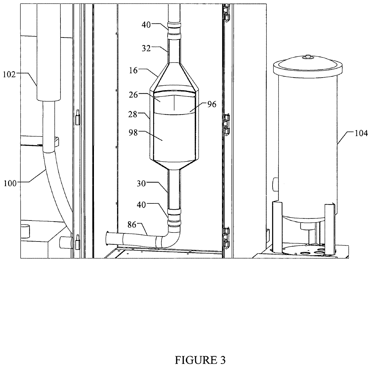
[0030]As can be seen with further reference to FIG. 1, each of the cleaning sections 12, 14 includes a cleaning chamber in which are placed the filters 16 being cleaned, and which are accessed at the front of the assembly via doors optionally having windows through which an operator can observe the filters and associated fittings during the cleaning process.

[0031]As will be described in greater detail below, the dry cleaning section provides cleaning of the filters using air or other gas as a fluid, and coll...


PUM

PropertyMeasurementUnit
massaaaaaaaaaa
pressuresaaaaaaaaaa
pressureaaaaaaaaaa

Abstract

An apparatus and method for cleaning ash / soot and other particulates from diesel particulate filters (DPF), including diesel oxidative catalysts (DOC) and similar exhaust components. Section for dry and wet cleaning include conduits that connect to the filters. For dry cleaning, a filter is mounted clean side up and air pressure is applied in opposite directions so that the particulate is dislodged and falls out. For wet cleaning, the filter is floated with a slug of liquid cleaning solution which is surged back-and-forth through the filter to dislodge and remove the particulate. The dry and wet cleaning sections may be combined or collocated, or may be located separately or used one without the other.

Description

RELATED APPLICATIONS[0001]This application claims the benefit of U.S. Provisional Patent Application Ser. No. 62 / 283,952 filed on Sep. 15, 2015.BACKGROUNDa. Field of the Invention[0002]The present invention relates generally to an apparatus for cleaning diesel exhaust particulate collectors, such as diesel particulate filters (DPF), diesel oxidation catalysts (DOC), and similar emission control components, and, more particularly, to a cleaning system that employs fluid pulses or surges applied to ends of a DPF, DOC or other diesel exhaust particulate collector to dislodge and remove accumulated material from the collector.b. Related Art[0003]Diesel particulate filters and similar emissions components are employed to collect noxious materials from exhaust streams of diesel engines, primarily in the form of particulates comprised mainly of soot. The most common types of diesel particulate filters (DPF) include wall-flow DPFs that are highly efficient in removing particulate, as well a...

Claims


Application Information

Patent Timeline
Patent Type & Authority Patents(United States)
IPC IPC(8): F01N3/023B01D41/04F01N3/035F01N9/00F02B3/06
CPCF01N3/023B01D41/04F01N3/0233F01N3/0237F01N3/035F01N9/002F02B3/06F02D2200/0812
Inventor SALSGIVER, ROBERT S.BENJAMIN, ROBERTMAJERLE, KELSON J.MCCOLLEY, KENT A.BOARD, JASON C.TAYLOR, RICHARD D.WALDO, COLE L.
Owner FSX EQUIP
Learn More