Left atrial appendage closure apparatus

a technology of appendage closure and left atrial appendage, which is applied in the direction of prosthesis, surgery, pharmaceutical delivery mechanism, etc., can solve the problems of bleeding risk, large limitations, and inability to occlusion the left atrial appendage by surgical procedure, and achieves stably fixed, stable fixation, and the effect of being effectiv

Active Publication Date: 2022-04-05
SHENZHEN KYD BIOMEDICAL TECH CO LTD
View PDF45 Cites 3 Cited by
  • Summary
  • Abstract
  • Description
  • Claims
  • Application Information

AI Technical Summary

Benefits of technology

[0011]Some embodiments aim to provide an effective, repositionable, stably fixed and fatigue resistant left atrial appendage closure apparatus for occluding the left atrial appendage (LAA) and blocking the outflow of thrombus in the left atrial appendage.

Problems solved by technology

Apart from the discomfort brought by the symptom of palpitation, the occurrence of the thromboembolism and other complications are the main hazards of atrial fibrillation.
Among all the methods, the occlusion of left atrial appendage by surgical procedure has not been widely used because of its great trauma and high risk.
At present, the most common means to prevent stroke in patients with atrial fibrillation is receiving long-term oral anticoagulant drugs, but the anticoagulant drugs will induce the bleeding risk and about 14% to 44% of patients fail to receive long-term anticoagulant therapy because of contraindications.
These types of left atrial appendage closure apparatus can all be inserted into the left atrial appendage through catheter intervention to achieve the occlusion effect of the left atrial appendage, but considerable limitations exist among all of them.
The inner wall of the left atrial appendage is uneven, the shape is irregular and the wall is thin, so it is difficult to realize both the non piercement of the wall and the solid fixation inside the left atrial appendage without falling off, and ultimately achieve the ideal occlusion effect.
But the lower anchorage strength of the braided fixation plate makes it difficult to adapt to the different shapes of the left atrial appendage.
Even if the anchor hook is sutured on the fixation plate, the fixation plate is also difficult to penetrate into the left atrial appendage wall under the condition of the extrusion deformation to achieve the stable fixation.
Moreover, the shape of the sealing plate will be affected by the extrusion deformation of fixed plate in the left atrial appendage, which leads to the poor sealing effect.
However, the cutting type of left atrial appendage closure apparatus is limited in the deformation capacity and fails to adapt to left atrial appendages with various shapes, which limit its application to a great extent.
After the cutting-type left atrial appendage closure apparatus is inserted into the left atrial appendage, the part in the left atrial appendage will usually form a depression with the atrial wall to form a new “left atrial appendage area”, which will increase the risk of new thrombosis.
But the anchor pins penetrated to the left atrium will be stuck to the edge of the sheath wall during the repeated positioning and the closure apparatus retrieval to induce the failure of closure apparatus retrieval and repeated positioning.
However, the sealing plate related to CN102805654A possesses a plane structure, which is not suitable for the sealing in the arc structure of the left atrium; in addition, the supporting rods of the anchor plate connect with each other and the deformation of the joint parts is large, which will induce large processing difficulty, poor fatigue resistant performance, brittleness in the human body and further resulting in the risk of cardiac perforation.
But the anchor pins penetrating into the left atrium will be stuck to the edge of the sheath wall in the process of repeated positioning and the closure apparatus retrieval, which leads to the failure of repeated positioning and the closure apparatus retrieval.
This instrument has poor fatigue strength in permanent implantation, is easy to break and pierce the heart and other tissues to further threaten the life of the patients.

Method used


Image

  • Left atrial appendage closure apparatus
  • Left atrial appendage closure apparatus
  • Left atrial appendage closure apparatus

Examples


embodiment 1

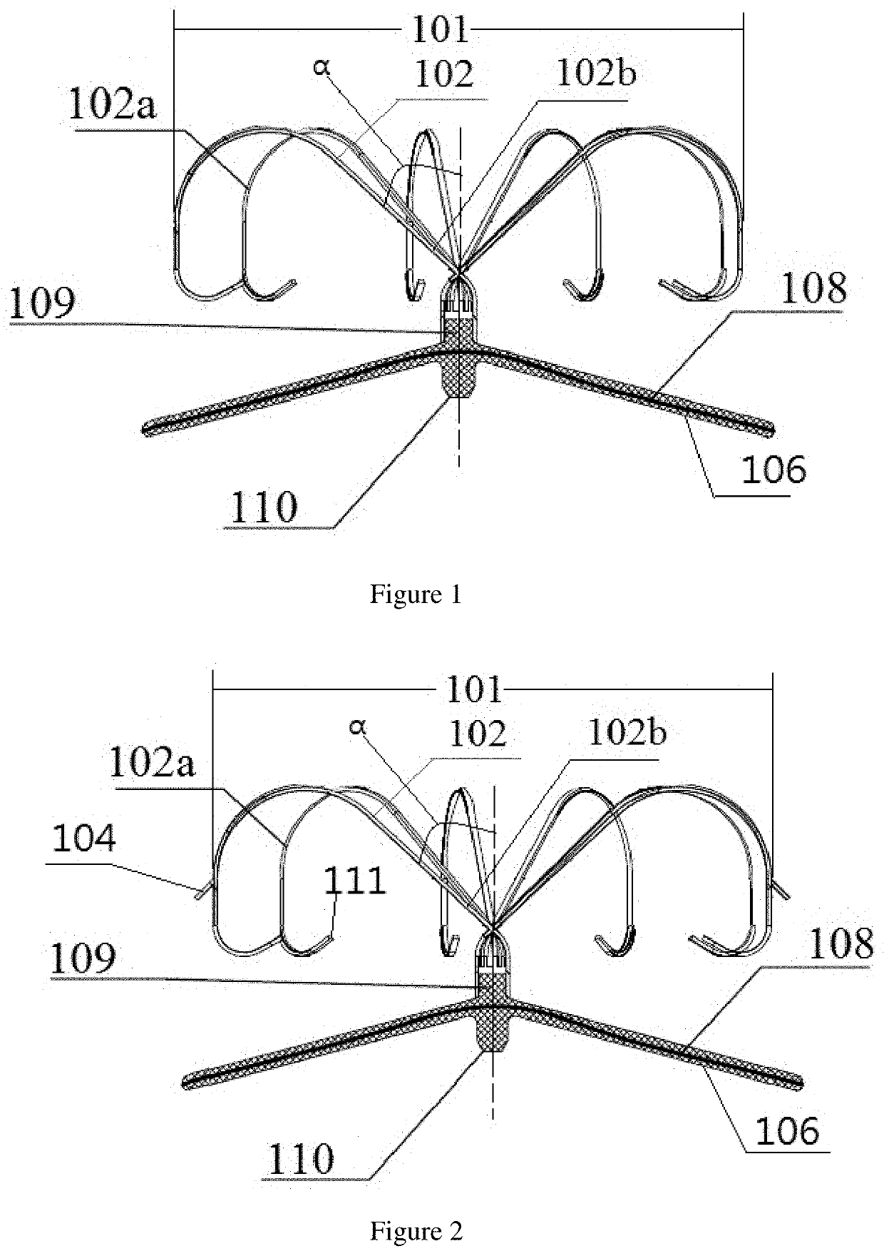
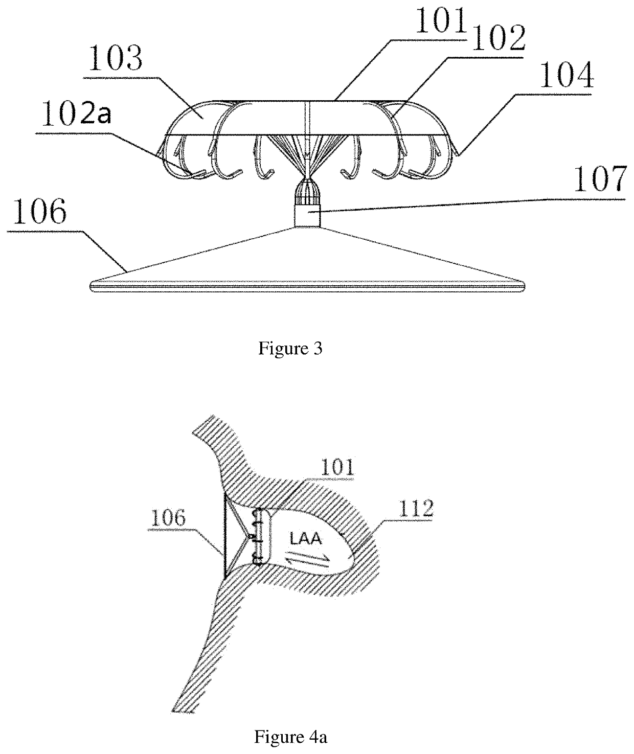
[0052]FIG. 1 describes a left atrial appendage closure apparatus, including a sealing plate 106 and an anchor plate 101 connected to the sealing plate.

[0053]The sealing plate is a mesh structure and arranged with a choke membrane 108 inside. The sealing plate's distal end is connected to a tubular member 109 and is connected with the anchor plate by the other end of the tubular member which is opposite the end connected to the sealing plate. The proximal end of the sealing plate is fixed with a fastener 110 and has a structure that can be connected to a convey device.

[0054]The end of the tubular member at the other side away from the end connected to the sealing plate is arranged with a plurality of supporting rods 102, the supporting rods originate from the direction away from the sealing plate and the proximal ends 102b of the supporting rods cross the tubular member center to the opposite side, the supporting rods intersect radially to form the anchor plate 101. The angle α betwe...

embodiment 2

[0055]A left atrial appendage closure apparatus described in FIG. 1 includes a sealing plate 106 and an anchor plate 101 connected to the sealing plate.

[0056]The sealing plate is a mesh structure and arranged with a choke membrane 108 inside. The sealing plate's distal end is connected to a tubular member 109 and is connected with the anchor plate by the other end of the tubular member which is opposite the end connected to the sealing plate. The proximal end of the sealing plate is fixed with a fastener 110 and has a structure which can be connected to a convey device.

[0057]The end of the tubular member at the other side away from the end connected to the sealing plate is arranged with a plurality of supporting rods 102. The supporting rods originate from the direction away from the sealing plate and the proximal ends 102b of the supporting rods cross the tubular member center to the opposite side. The supporting rods intersect radially to form the anchor plate 101. The angle α bet...

embodiment 3

[0059]A left atrial appendage closure apparatus described in FIG. 2 includes a sealing plate 106 and an anchor plate 101 connected to the sealing plate.

[0060]The sealing plate is a mesh structure and arranged with a choke membrane 108 inside. The sealing plate's distal end is connected to a tubular member 109 and is connected with the anchor plate by the other end of the tubular member which is opposite the end connected to the sealing plate, the proximal end of the sealing plate is connected to a fastener 110 and has a structure which can be connected to a convey device.

[0061]The end of the tubular member at the other side away from the end connected to the sealing plate is arranged with a plurality of supporting rods 102. The supporting rods originate from the direction away from the sealing plate and the proximal ends 102b of the supporting rods cross the tubular member center to the opposite side. The supporting rods intersect radially to form the anchor plate 101. The angle α b...


PUM

PropertyMeasurementUnit
angleaaaaaaaaaa
heightaaaaaaaaaa
heightaaaaaaaaaa

Abstract

A left atrial appendage closure apparatus for obstructing the left atrial appendage, comprises a sealing plate and an anchor plate. The sealing plate is a mesh structure and arranged with a choke membrane inside. In addition, the sealing plate adopts a tubular member for distal fixation and is connected with the anchor plate by the tubular member. The proximal end of the sealing plate is fixed with a fastener and is provided with a structure to connect to a convey device. The end of the tubular member at the other side away from the end connected to the sealing plate is arranged with a plurality of supporting rods, which intersect radially to form the anchor plate.

Description

CROSS-REFERENCE TO RELATED PATENT APPLICATIONS[0001]This application is a U.S. National Phase Application under 35 U.S.C. § 371 of International Patent Application No. PCT / CN2016 / 112062, filed Dec. 26, 2016, and claims the priority of Chinese Application Nos. 201610119169.8, Mar. 2, 2016 and 201511003714.9, filed Dec. 29, 2015, all of which are incorporated by reference in their entireties. The International Application was published on Jul. 6, 2017 as International Publication No. WO 2017 / 114348 A1.TECHNICAL FIELD[0002]The present invention relates to an implantable medical device and in particular relates to a highly effective left atrial appendage closure apparatus. The apparatus can be deployed repeatedly and stably fixed. It is fatigue-resistant and can occlude the left atrial appendage and obstruct the outflow of thrombus in the left atrial appendage.BACKGROUND ART[0003]At present, with the development of the interventional apparatus, many untreatable diseases with surgery hav...

Claims


Application Information

Patent Timeline
Patent Type & Authority Patents(United States)
IPC IPC(8): A61B17/12A61L31/06A61B17/00A61L31/14
CPCA61B17/12122A61B17/0057A61B17/12031A61B17/12172A61B17/12177A61L31/06A61L31/14A61B17/12145A61B2017/00575A61B2017/00579A61B2017/00592A61B2017/00597A61B2017/00615A61B2017/00938A61L2400/18A61B17/1215A61B2017/00796A61B2017/00831A61B2017/1205C08L67/02A61B17/12A61F2/00
Inventor CHEN, YILONGHUANG, WEI
Owner SHENZHEN KYD BIOMEDICAL TECH CO LTD
Why Eureka
Try Eureka