Bottom gas purge unit, load port apparatus, and bottom gas purge method

a gas purge unit and gas purge method technology, applied in the direction of chemistry apparatus and processes, cleaning processes and utensils, basic electric elements, etc., can solve the problems of gas leakage from the gap between the nozzle and the nozzle, etc., to prevent gas leakage

Active Publication Date: 2022-03-15
TDK CORPARATION
View PDF4 Cites 0 Cited by
  • Summary
  • Abstract
  • Description
  • Claims
  • Application Information

AI Technical Summary

Benefits of technology

[0011]Since the bottom gas purge device according to the present invention includes the pressure sensor provided at the tip end portion of the nozzle, the pressure at which the nozzle is connected to the purge port can be detected. Therefore, such a bottom gas purge device can connect the nozzle and the purge port at an appropriate pressure, and can prevent gas leakage due to a connection failure between the nozzle and the purge port and prevent the purge port from being pushed upward excessively strongly by the nozzle.
[0013]In such a bottom gas purge device, the connection between the nozzle and the purge port can be reliably detected, so that the gas leakage due to the connection failure between the nozzle and the purge port can be more preferably prevented.
[0015]The bottom gas purge device including such a pressure sensor can detect that the nozzle is connected to the purge port in an inclined state. Therefore, in a case where the nozzle is inclined with respect to the purge port, such a bottom gas purge device can prevent bottom gas purging from being performed in the inclined state, for example, by redoing an connection operation of the nozzle. In addition, in such a bottom gas purge device, the gas can be preferably prevented from leaking from a gap between the nozzle and the purge port that are connected in the inclined state.
[0017]Such a bottom gas purge device can reliably detect a state in which the nozzle is pressed against the purge port in the inclined state. Therefore, such a bottom gas purge device can reliably prevent the gas from leaking from the gap between the nozzle and the purge port that are connected in the inclined state. In addition, when the abnormal connection is detected, the purge port can be more preferably prevented from being pushed upward excessively strongly by the nozzle by stopping the connection operation or the like.
[0021]Such a load port apparatus can preferably take out and put in the substrate from and into the main opening by preventing the container from being inclined with respect to the mounting table, and can preferably prevent the gas from leaking from the gap between the nozzle and the purge port.
[0027]According to the bottom gas purge method of the present invention, the pressure sensor provided at the tip end portion of the nozzle can detect the pressure at which the nozzle is connected to the purge port. Therefore, according to such a bottom gas purge method, the nozzle and the purge port can be connected at an appropriate pressure, and it is possible to prevent gas leakage due to a connection failure between the nozzle and the purge port and to prevent the purge port from being pushed upward excessively strongly by the nozzle during an connection operation.

Problems solved by technology

However, in the bottom gas purge device in related art, connection between the nozzle and the purge port may be insufficient, and the gas may leak from a gap between the nozzle and the purge port.
In such a case, efficiency of the bottom gas purge may be lowered, and the leaked gas may excessively reduce oxygen concentration around the device in the factory.
However, in this case, the entire container is pushed upward by a force of pressing the nozzle against the bottom portion of the container, which causes the container to be inclined with respect to a mounting table.

Method used


Image

  • Bottom gas purge unit, load port apparatus, and bottom gas purge method
  • Bottom gas purge unit, load port apparatus, and bottom gas purge method
  • Bottom gas purge unit, load port apparatus, and bottom gas purge method

Examples


Embodiment Construction

[0036]Hereinafter, the present invention will be described based on an embodiment shown in the drawings.

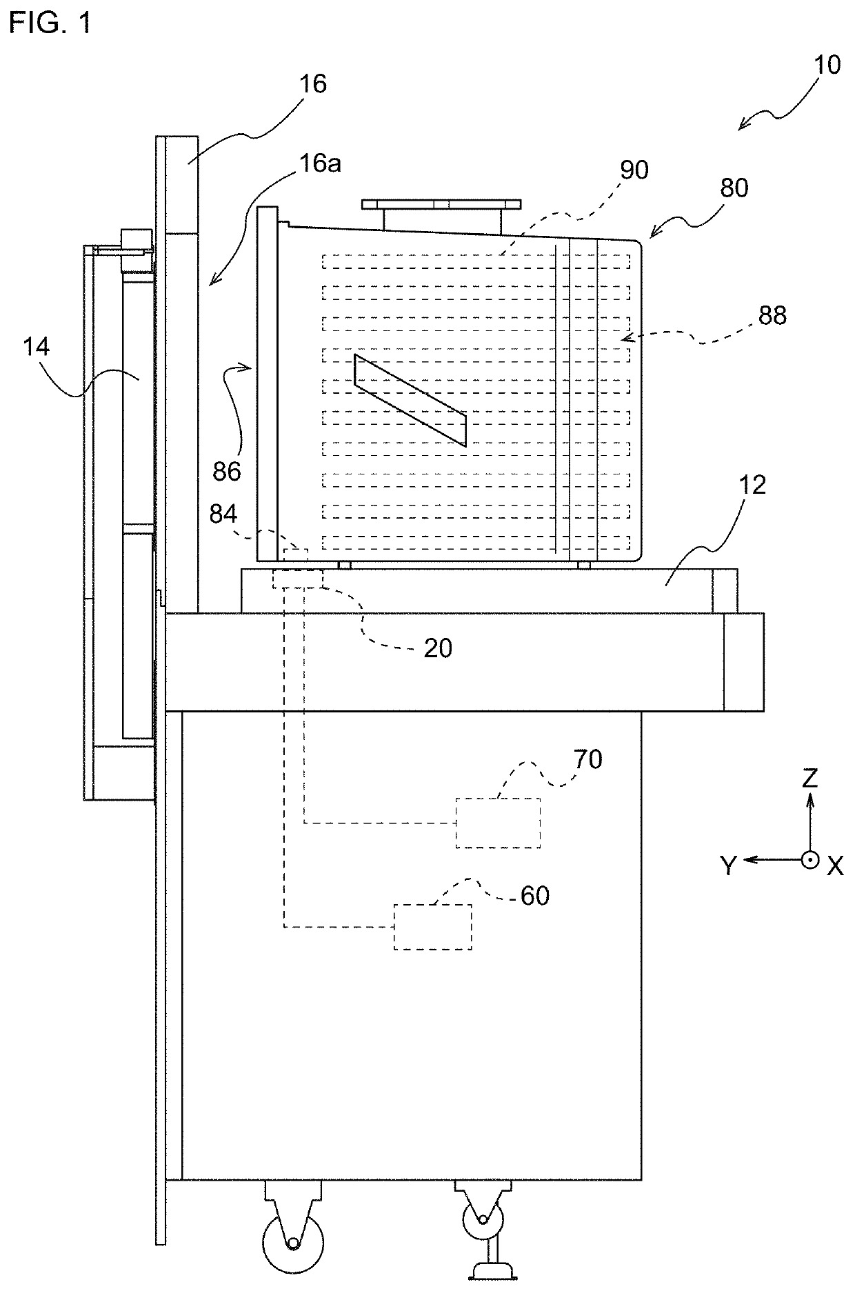
[0037]FIG. 1 is an external view showing a load port apparatus 10 including a bottom gas purge device 20 according to an embodiment of the present invention and a FOUP 80 serving as a container mounted on a mounting table 12. The bottom gas purge device 20 is provided in, for example, the load port apparatus 10 installed in a wall portion of an EFEM, a stocker that stores the FOUP 80 or the like. However, the bottom gas purge device 20 may be provided in other devices that purge gas.

[0038]The load port apparatus 10 shown in FIG. 1 constitutes a part of the EFEM. The EFEM forms a mini-environment where a robot arm or the like for wafer transfer is provided. The robot arm takes out a substrate 90 such as a silicon wafer accommodated in the FOUP 80 from the FOUP 80 connected to the mini-environment by the load port apparatus 10, and transports the substrate 90 to a semiconductor proc...


PUM


Abstract

Provided is a bottom gas purge device including a nozzle that can be appropriately connected to a purge port. A bottom gas purge device configured to introduce a cleaning gas into a container from a bottom portion of the container accommodating a substrate includes: a mounting table on which the container is mounted; a nozzle provided so as to be movable relative to the mounting table in an upward-downward direction and connectable from below to a purge port provided in the bottom portion of the container; a gas supply unit configured to supply the cleaning gas to the nozzle; and a pressure sensor provided at a tip end portion of the nozzle and configured to detect a pressure rising between the purge port and the nozzle when the nozzle is connected to the purge port.

Description

BACKGROUND OF THE INVENTIONField of the Invention[0001]The present invention relates to a bottom gas purge device and the like that perform gas purging from a bottom portion of the container on the container that transports a substrate.Description of the Related Art[0002]In a semiconductor factory or the like, a substrate is transported and stored in the factory by using a container in which the substrate such as a silicon wafer is accommodated. Although the container is sealed, cleanliness in the container may decrease due to outgas generated from the accommodated substrate and leakage or gas permeation from the sealed portion.[0003]Accordingly, in recent years, a load port apparatus that delivers a container in a semiconductor factory has been propose to include a bottom gas purge device that performs gas purging from a bottom portion of the container. (JP-A-2011-187539) The bottom gas purge device can connect a nozzle to a purge port provided at the bottom portion of the containe...

Claims


Application Information

Patent Timeline
Patent Type & Authority Patents(United States)
IPC IPC(8): B08B9/08B08B5/00H01L21/673
CPCB08B9/08B08B5/00H01L21/67389B08B2209/08H01L21/67393
Inventor IWAMOTO, TADAMASA
Owner TDK CORPARATION
Why Eureka
Try Eureka