Luminescent solar concentrators and related methods of manufacturing
What is Al technical title?
Al technical title is built by PatSnap Al team. It summarizes the technical point description of the patent document.
a technology of solar concentrators and solar energy, applied in the direction of basic electric elements, electrical equipment, semiconductor devices, etc., can solve the problems of limiting the dissemination of solar power into the global energy market, reducing the economic viability of pv technology, and reducing the use of gathered ligh
Active Publication Date: 2022-01-18
CALIFORNIA INST OF TECH +2
View PDF66 Cites 2 Cited by
Summary
Abstract
Description
Claims
Application Information
AI Technical Summary
This helps you quickly interpret patents by identifying the three key elements:
Both the strict DNI requirement and the high LCOE of Si—PV cells ultimately limit the dissemination of solar power into the global energy market.
However, some of the gathered light may not be useable due to losses from absorption and escaped light.
However, LSCs have not yet reached commercialization for photovoltaic power generation, largely due to their comparatively low power conversion efficiencies (“PCEs”) and lack of scalability.
Method used
Image
Click on the blue label to locate the original text in one second.
Reading with bidirectional positioning of images and text.
Examples
Embodiment Construction
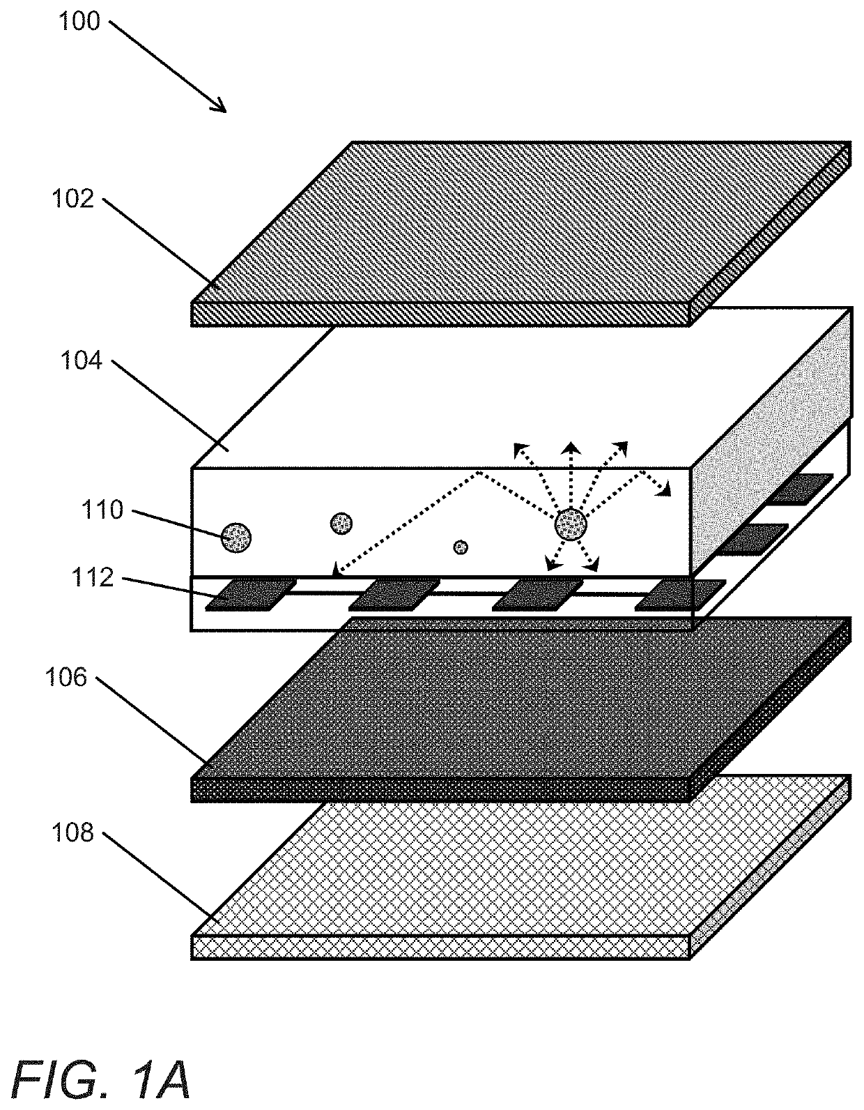
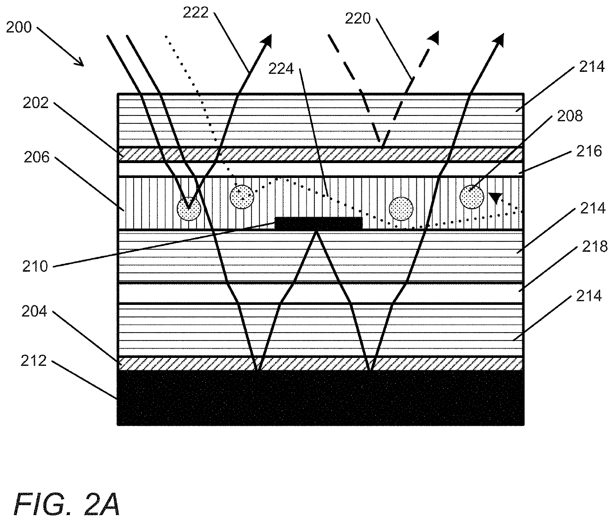
[0043]Luminescent solar concentrators offer a unique solution to capture sunlight and to reduce the overall Levelized Cost of Electricity. LSC module efficiency can suffer from two key loss mechanisms. First, embedded luminophores can require near-unity photoluminescence quantum yield (“PLQY”) in order to achieve desired optical efficiencies. To prevent further luminophore parasitic absorption, separation between absorbed and emitted photon energies (i.e., the Stokes shift) should be maximized. Historically, luminophores have not been able to maintain high enough PLQY and large Stokes shifts. Thus, many incident photons are usually parasitically absorbed by the luminophores in traditional devices. Second, the index of refraction contrast between the optical waveguide and the surrounding medium can limit complete photon trapping. Polymer waveguides experience significant escape cone losses for photons radiated at angles that lie between normal incidence and the critical angle of the ...
PUM
Property
Measurement
Unit
radii
aaaaa
aaaaa
radii
aaaaa
aaaaa
thicknesses
aaaaa
aaaaa
Abstract
Luminescent solar concentrators in accordance with various embodiments of the invention can be designed to minimize photon thermalization losses and incomplete light trapping using various components and techniques. Cadmium selenide core, cadmium sulfide shell (CdSe / CdS) quantum dot (“QD”) technology can be implemented in such devices to allow for near-unity QDs and sufficiently large Stokes shifts. Many embodiments of the invention include a luminescent solar concentrator that incorporates CdSe / CdS quantum dot luminophores. In further embodiments, anisotropic luminophore emission can be implemented through metasurface / plasmonic antenna coupling. In several embodiments, red-shifted luminophores are implemented. Additionally, top and bottom spectrally-selective filters, such as but not limited to selectively-reflective metasurface mirrors and polymeric stack filters, can be implemented to enhance the photon collection efficiency. In some embodiments, luminescent solar concentrator component is optically connected in tandem with a planar Si subcell, forming a micro-optical tandem luminescent solar concentrator.
Description
CROSS-REFERENCE TO RELATED APPLICATIONS[0001]The current application claims the benefit of and priority under 35 U.S.C. § 119(e) to U.S. Provisional Patent Application No. 62 / 550,115 entitled “Micro-Optical Tandem Luminescent Solar Concentrator,” filed Aug. 25, 2017. The disclosure of U.S. Provisional Patent Application No. 62 / 550,115 is hereby incorporated by reference in its entirety for all purposes.STATEMENT REGARDING FEDERALLY SPONSORED RESEARCH OR DEVELOPMENT[0002]This invention was made with government support under Grant No(s). DE-AR0000627, 113808, S-143159 and DE-ACO2-05CH11231 awarded by the Department of Energy. The government has certain rights in the invention.FIELD OF THE INVENTION[0003]The present invention generally relates to luminescent solar concentrators and, more specifically, to luminescent solar concentrators with embedded luminophores.BACKGROUND[0004]Silicon photovoltaic (“Si—PV”) modules currently dominate the solar energy market. Increased progress into Si...
Claims
Application Information
Patent Timeline
Application Date:The date an application was filed.
Publication Date:The date a patent or application was officially published.
First Publication Date:The earliest publication date of a patent with the same application number.
Issue Date:Publication date of the patent grant document.
PCT Entry Date:The Entry date of PCT National Phase.
Estimated Expiry Date:The statutory expiry date of a patent right according to the Patent Law, and it is the longest term of protection that the patent right can achieve without the termination of the patent right due to other reasons(Term extension factor has been taken into account ).
Invalid Date:Actual expiry date is based on effective date or publication date of legal transaction data of invalid patent.