
Control device for vehicle

a control device and vehicle technology, applied in the direction of vehicle position/course/altitude control, process and machine control, instruments, etc., can solve the problems of vibration of the vehicle, sudden acceleration or deceleration of the vehicle, affecting the comfort of riding in the vehicle, etc., to achieve smooth switching of driving mode and simple configuration

Active Publication Date: 2022-01-04
HONDA MOTOR CO LTD
View PDF3 Cites 0 Cited by
  • Summary
  • Abstract
  • Description
  • Claims
  • Application Information

AI Technical Summary

Benefits of technology

Enables smooth mode switching without sudden vehicle movements, maintaining a stable gear range for a predetermined period and adjusting based on driver input, thus preventing unexpected acceleration or deceleration and vibration, while keeping the configuration simple and cost-effective.

Problems solved by technology

In this case, if there is a large difference between the driving force of the vehicle in the automated driving mode and the driving force that the driver of the vehicle requests in the manual driving mode, there is a concern that sudden acceleration or deceleration of the vehicle and vibration of the vehicle will occur if a gear change operation in accordance with the requested driving force is performed, and there is a concern that this will affect the comfort of riding in the vehicle.
However, if the actuator is provided in the vehicle, there are problems that the number of components increases, and this leads to an increase in size of the device and an increase in costs.

Method used


Image

  • Control device for vehicle
  • Control device for vehicle
  • Control device for vehicle

Examples


Embodiment Construction

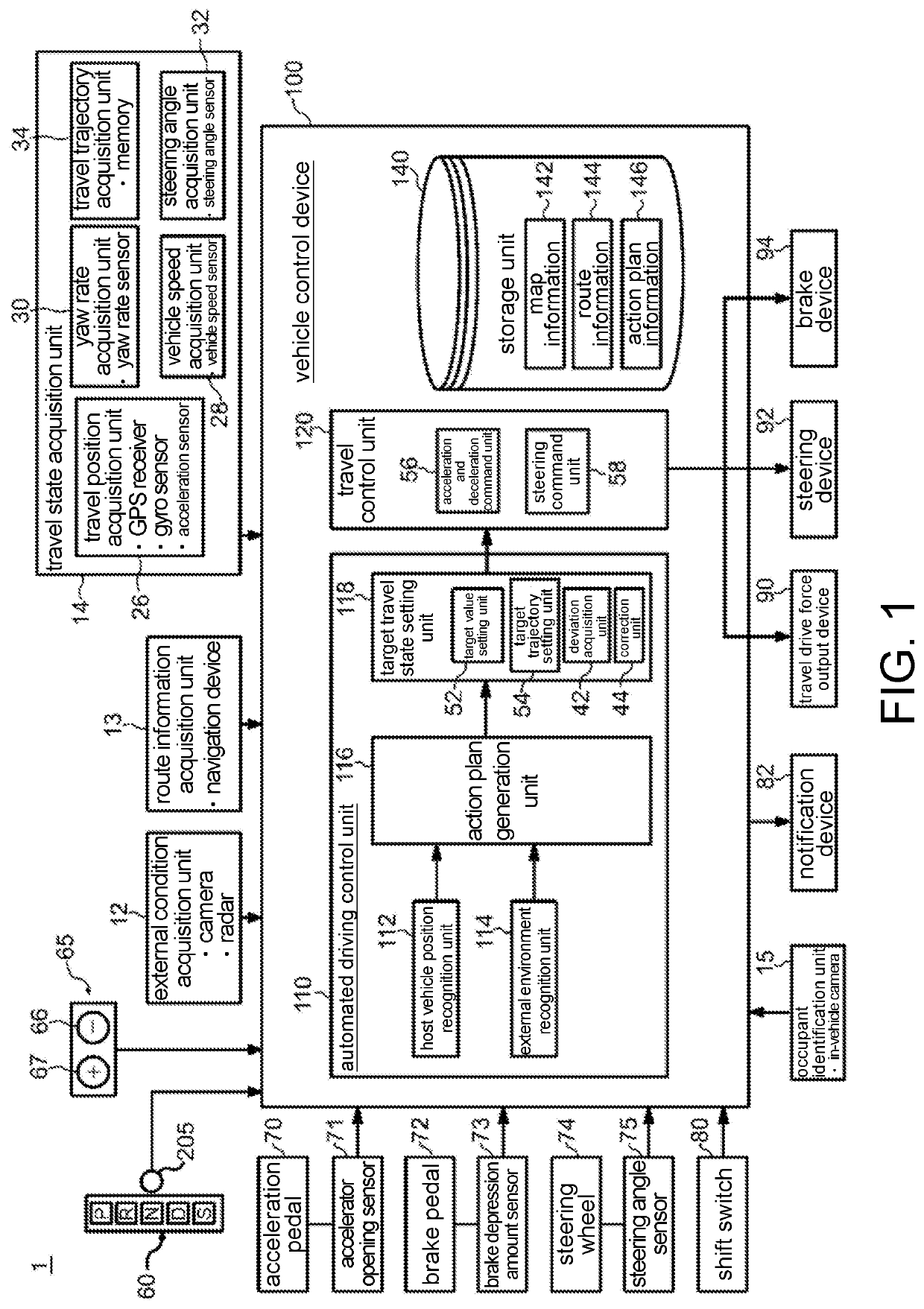
[0039]Hereinafter, embodiments of the disclosure will be described with reference to the accompanying drawings. FIG. 1 is a functional configuration diagram of a vehicle control device 100 mounted in a vehicle 1. A configuration of the vehicle control device 100 will be described using the drawing. The vehicle 1 (host vehicle) in which the vehicle control device 100 is mounted is, for example, a vehicle with two wheels, three wheels, four wheels, or the like and includes a vehicle using an internal combustion engine as a power source, an electric vehicle using an electric motor as a power source, a hybrid vehicle that includes both an internal combustion engine and an electric motor, and the like. Also, the aforementioned electric vehicle is driven using electric power discharged by a battery such as a secondary battery, a hydrogen fuel battery, a metal fuel battery, or an alcohol fuel battery, for example.

[0040]The control device 100 includes a mechanism for taking various kinds of...


PUM


Abstract

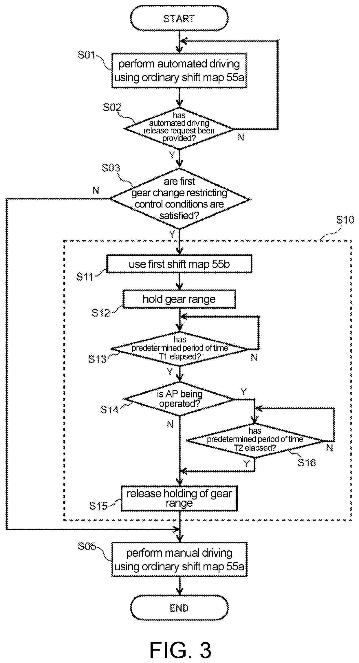
A control device for a vehicle capable of switching between an automated driving mode in which driving force of a vehicle having a transmission is automatically controlled and a manual driving mode in which the driving force of the vehicle is controlled on the basis of a driver's operation on the vehicle includes: an operation element to which the driver's operation is input; and a travel control unit that outputs a command value for selecting a gear range of the transmission. The travel control unit selects which of ordinary gear change control and gear change restricting control is to be performed on the basis of an operation performed on the operation element when there is an automated driving release request in which the automated driving mode is released and the automated driving mode is switched to the manual driving mode during traveling of the vehicle in the automated driving mode.

Description

CROSS-REFERENCE TO RELATED APPLICATION[0001]This application claims the priority benefit of Japan application serial no. 2018-082478, filed on Apr. 23, 2018. The entirety of the above-mentioned patent application is hereby incorporated by reference herein and made a part of this specification.BACKGROUNDTechnical Field[0002]The disclosure relates to a control device for a vehicle and particularly to a control device for a vehicle that performs automated driving control for automatically controlling the driving force of a vehicle.Description of Related Art[0003]In the related art, there is a control device for a vehicle that includes an automated driving control unit for automatically controlling a host vehicle such that the host vehicle travels along a route to a destination as illustrated in Patent Document 1, for example. According to such a control device for a vehicle for automated driving control, it is necessary to shift the driving force of the vehicle from a driving force of ...

Claims


Application Information

Patent Timeline
Patent Type & Authority Patents(United States)
IPC IPC(8): B60W50/08G05D1/00B60W10/20B60W10/10B60W10/06B60W20/30
CPCB60W50/087B60W10/06B60W10/10B60W10/20B60W20/30G05D1/0061B60W30/182B60W50/082B60W10/04B60W2050/007B60W2050/0054F16H2061/0227F16H61/0213B60W60/0053
Inventor ADACHI, TAKASHIARAI, KENTARONOGUCHI, TOMOYUKISADAKIYO, MASAYUKIISHIKAWA, HISASHI
Owner HONDA MOTOR CO LTD
Learn More