
QoS control device in multi-wireless network environment for video transmission and a controlling method thereof

a multi-wireless network and control device technology, applied in the direction of wireless communication, transmission path division, selective content distribution, etc., can solve the problems of data transmission rate deterioration, communication may not be normally performed, data transmission rate may be very low, etc., to achieve efficient control of qos and flow, the effect of high quality

Active Publication Date: 2021-12-28
SAMSUNG ELECTRONICS CO LTD
View PDF20 Cites 0 Cited by
  • Summary
  • Abstract
  • Description
  • Claims
  • Application Information

AI Technical Summary

Benefits of technology

The patent is about a transmission system that uses low speed and high speed wireless networks to send high quality video without interruptions. The system efficiently controls quality of service and flow to ensure the video is transmitted without any problems. The technical effect of this invention is to improve video transmission over wireless networks and provide better service to users.

Problems solved by technology

However, in an environment where the LOS is not guaranteed (non-line-of-sight (NLOS)), communication may not be normally performed or the data transmission rate may be very low.
Therefore, there is a problem in that the data transmission rate is deteriorated, since the bands are influenced by interference due to the technology of using radio frequency bands such as Bluetooth, or the presence of many APs, recently.
The WiGig is less influenced by interference, but there is a problem in that communication may not be available in the non-line-of-sight (NLOS) environment in which an obstacle exists between transmitting and receiving antennas.
When a video transmission environment is constructed using a wireless network, the related art Wi-Fi has a problem in that it is difficult to transmit high quality contents due to interference by other APs and Bluetooth, or the like.
When the WiGig is used, it is relatively easy to transmit high quality contents because of high transmission rate, but there is a limitation that there should be no obstacle between a transmitting antenna and a receiving antenna.
When using the FST technology, there is an advantage that WiGig and Wi-Fi may complement each other, but this is intended to maintain connectivity and thus has a problem that it is not suitable for video transmission.
As a result, in the WiGig, there is a time delay until the NLOS situation is recognized and connection is converted to Wi-Fi and a disconnection of streaming or deterioration in image quality occurs.
In addition, since WiGig and Wi-Fi operate independently of each other, there is an inefficiency in terms of quality of service (QoS) control, because WiGig converts the network packet flow to the Wi-Fi through FST in a situation where the WiGig is not aware of the Wi-Fi network situation.
Further, the transmitter may not identify the video reception status of the receiver, and thus, there is a problem in that it is impossible to control the traffic, in preparation for the disconnection.

Method used


Image

  • QoS control device in multi-wireless network environment for video transmission and a controlling method thereof
  • QoS control device in multi-wireless network environment for video transmission and a controlling method thereof
  • QoS control device in multi-wireless network environment for video transmission and a controlling method thereof

Examples


Embodiment Construction

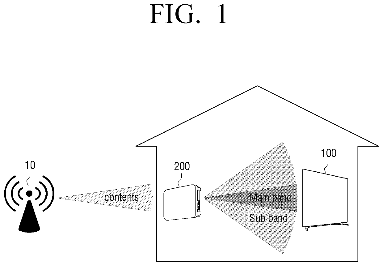
[0047]Hereinafter, embodiments of the disclosure will be described with reference to the accompanying drawings. However, it may be understood that the disclosure is not limited to embodiments described hereinafter, but includes various modifications, equivalents, and / or alternatives of these embodiments. In relation to explanation of the drawings, similar drawing reference numerals may be used for similar constituent elements.

[0048]In the description, the terms “first,”“second,” and so forth are used to describe diverse elements regardless of their order and / or importance and to discriminate one element from other elements, but are not limited to the corresponding elements. For example, a first user appliance and a second user appliance may indicate different user appliances regardless of their order or importance. For example, without departing from the scope as described herein, a first element may be referred to as a second element, or similarly, a second element may be referred ...


PUM


Abstract

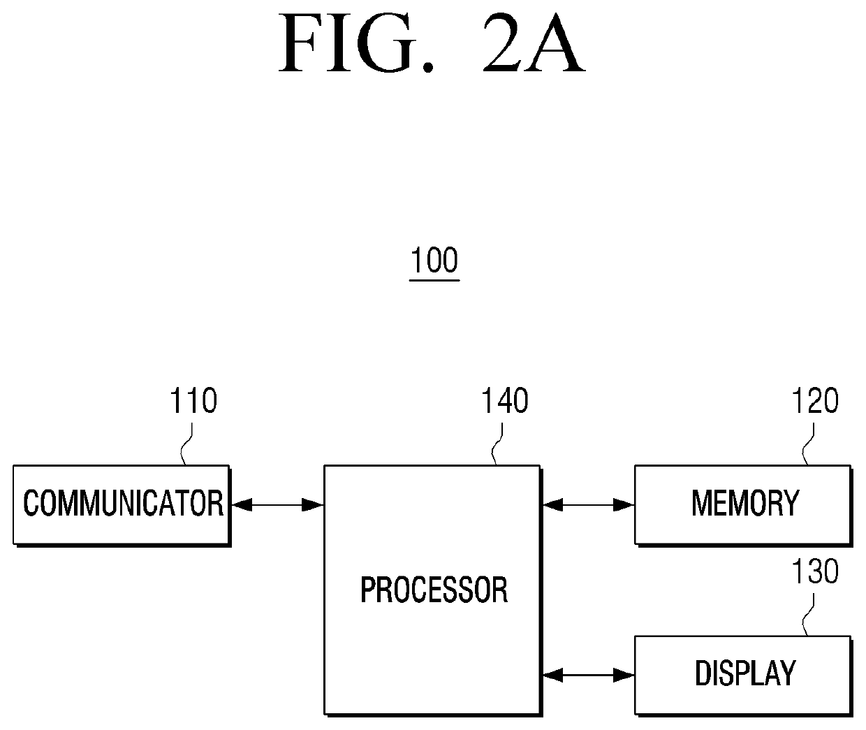
Disclosed is an electronic device performing a video transmission using a multi-wireless network and a controlling method thereof. The electronic device for receiving and reproducing contents includes: a communicator, and a processor to receive, from an external device, a signal including original data of contents through a main frequency band, and receive, from an external device through at least one sub frequency band, a connection state signal including information on original data, and control the communicator to transmit, to the external device through the main frequency band and the at least one sub frequency band, a response signal including information on whether original data is missing, and an amount of received data stored in a buffer.

Description

CROSS-REFERENCE TO RELATED APPLICATION(S)[0001]This application is based on and claims priority under 35 U.S.C. § 119 to Korean Patent Application No. 10-2018-0109477, filed on Sep. 13, 2018, in the Korean Intellectual Property Office, the disclosure of which is incorporated by reference herein in its entirety.BACKGROUND1. Field[0002]The disclosure relates to an electronic device performing video transmission using a multi-wireless network and a controlling method thereof, and more particularly, a video transmission in which high quality video is reproduced without disconnection using a network by efficiently transmitting a video using different wireless networks of two or more types.2. Description of Related Art[0003]Wi-Fi refers to an enabling technology that provides a network wirelessly using frequencies in a 2.4 GHz band and a 5 GHz band. A regular Wi-Fi network includes a terminal to be connected to a network, and an access point (AP) that is connected to a wired network, mana...

Claims


Application Information

Patent Timeline
Patent Type & Authority Patents(United States)
IPC IPC(8): H04L5/00H04W28/20H04N21/4363H04W76/15H04W72/04
CPCH04L5/0094H04L5/0046H04N21/43637H04W28/20H04W72/0453H04W76/15H04L5/0044H04L5/0005H04L1/1671H04L1/1819H04L1/1861H04L1/1893H04L1/1838H04L1/0017H04N21/4381H04N21/4382H04N21/2383
Inventor PARK, SUNHOPARK, JUNGHYUNLEE, JOONYOUNG
Owner SAMSUNG ELECTRONICS CO LTD
Learn More