System and method for generating a three-dimensional body

Active Publication Date: 2021-11-23
STADLMANN KLAUS
View PDF11 Cites 0 Cited by
  • Summary
  • Abstract
  • Description
  • Claims
  • Application Information

AI Technical Summary

Benefits of technology

The invention relates to a system for generating three-dimensional objects using stereolithography. The system aims to overcome the limitations of existing systems by facilitating an easier, quicker, exact, continuous and / or non-continuous process, even at low layer thicknesses and large exposure areas. It solves the problem of transporting a new photosensitive substance into the gap caused by the lifting of the layer formed last. The system also allows for a higher profitability, enabling both continuous and non-continuous processes. The system includes a semipermeable layer which creates a transport ability for a new photoreactive substance, allowing it to enter the gap between the layer and the component layer formed last. The system can also have a geometric driver elevation that permits an efficient and intelligent conveyance of the photoreactive substance, facilitating its transport even when it is paste-like.

Problems solved by technology

In systems which provide for an exposure to light from below, see for instance DE 10 2013 215 040 A1, one of the greatest problems is the removal or detachment of the just generated component layers without destroying the component thereby and allowing that a new photosensitive liquid will flow into the gap between the component layer and the reference surface.
When the component is severed from the base plate of the trough such that a secure removal is possible, this has negative effects on the speed of the construction process.
By said methods there is, however, not allowed any continuous process, and, thus, they increase the times of construction for the object.
In particular in case of large component surfaces this results in an insufficient transport of new photosensitive liquid into the gap.
When multiphase systems are used, the boundary surface is also unstable, and a formation of corrugations or rippling or the like can occur.
Said arrangement has, however, disadvantages with regard to the handling during operation.
The known techniques have the disadvantage, among others, that in case of the non-continuous generation of a component an indentation pad is produced in the carrier phase in dependence on the geometric layer information, which leads to a distortion or to an accummulating defect in the component.
Furthermore, in the non-continuous operation the process speed is restricted by the component which is movable along the phase boundary.
Also the material of which the component which moves along the phase boundaries consists is restricted by the chemical properties of both phases (corrosion).
Moreover, the cleaning of the component as well as of the trough is quite expensive.
The process stability in case of a direct contact of two phases leads to undesired effects during the entire process time, for instance to inclusions of the carrier phase in the cured component layer as well as to a component quality which is dependent on the cross-section.

Method used


Image

  • System and method for generating a three-dimensional body
  • System and method for generating a three-dimensional body
  • System and method for generating a three-dimensional body

Examples


Embodiment Construction

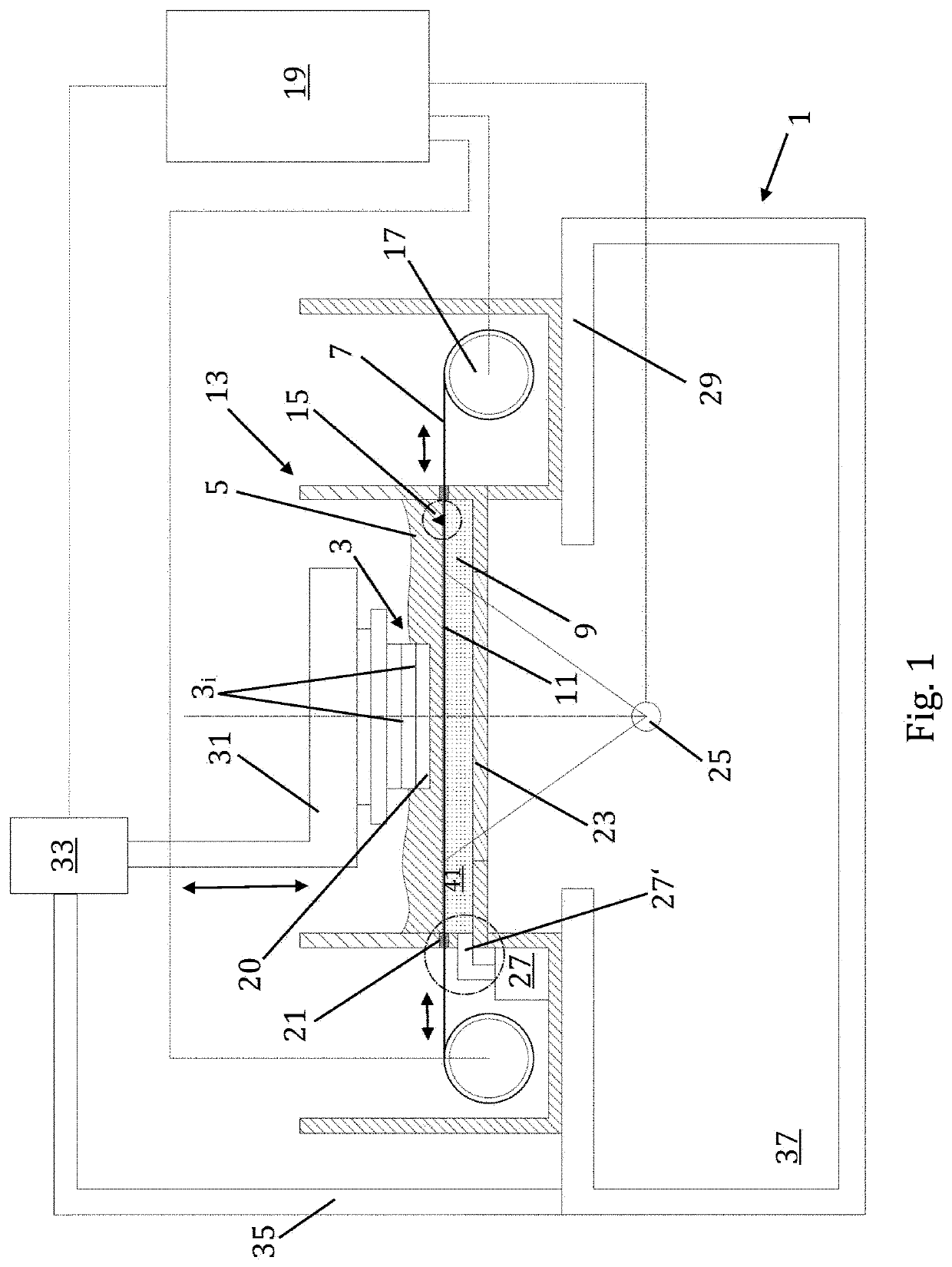
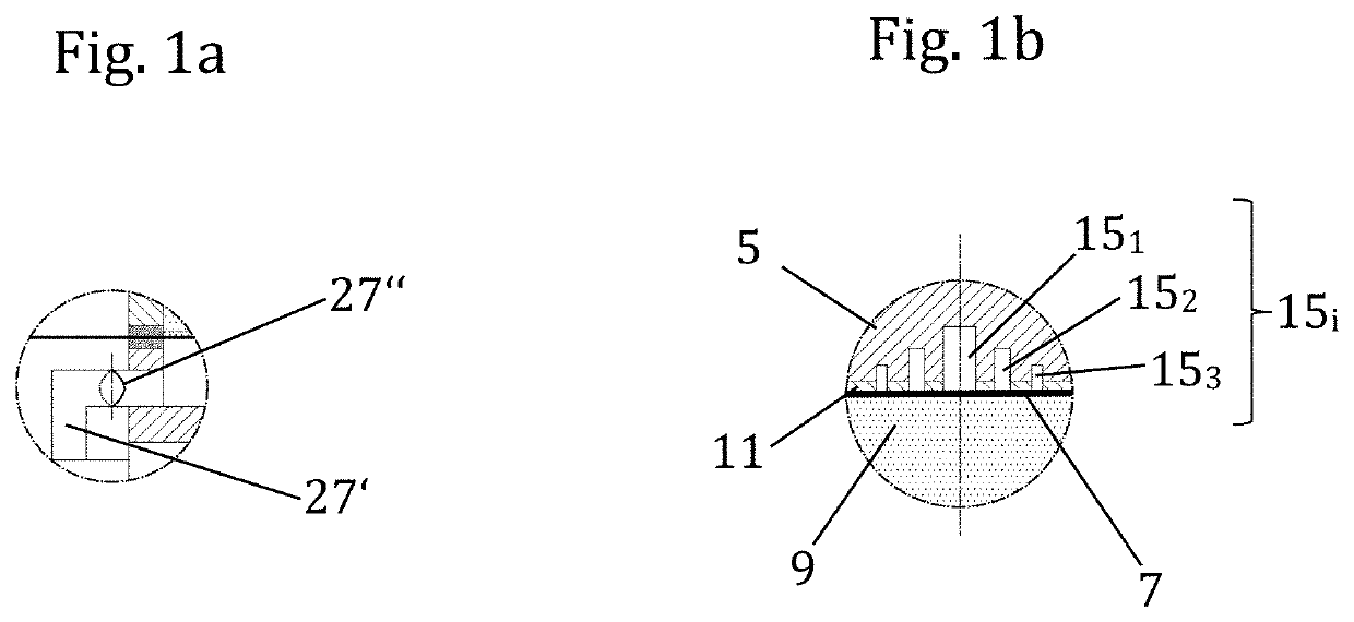
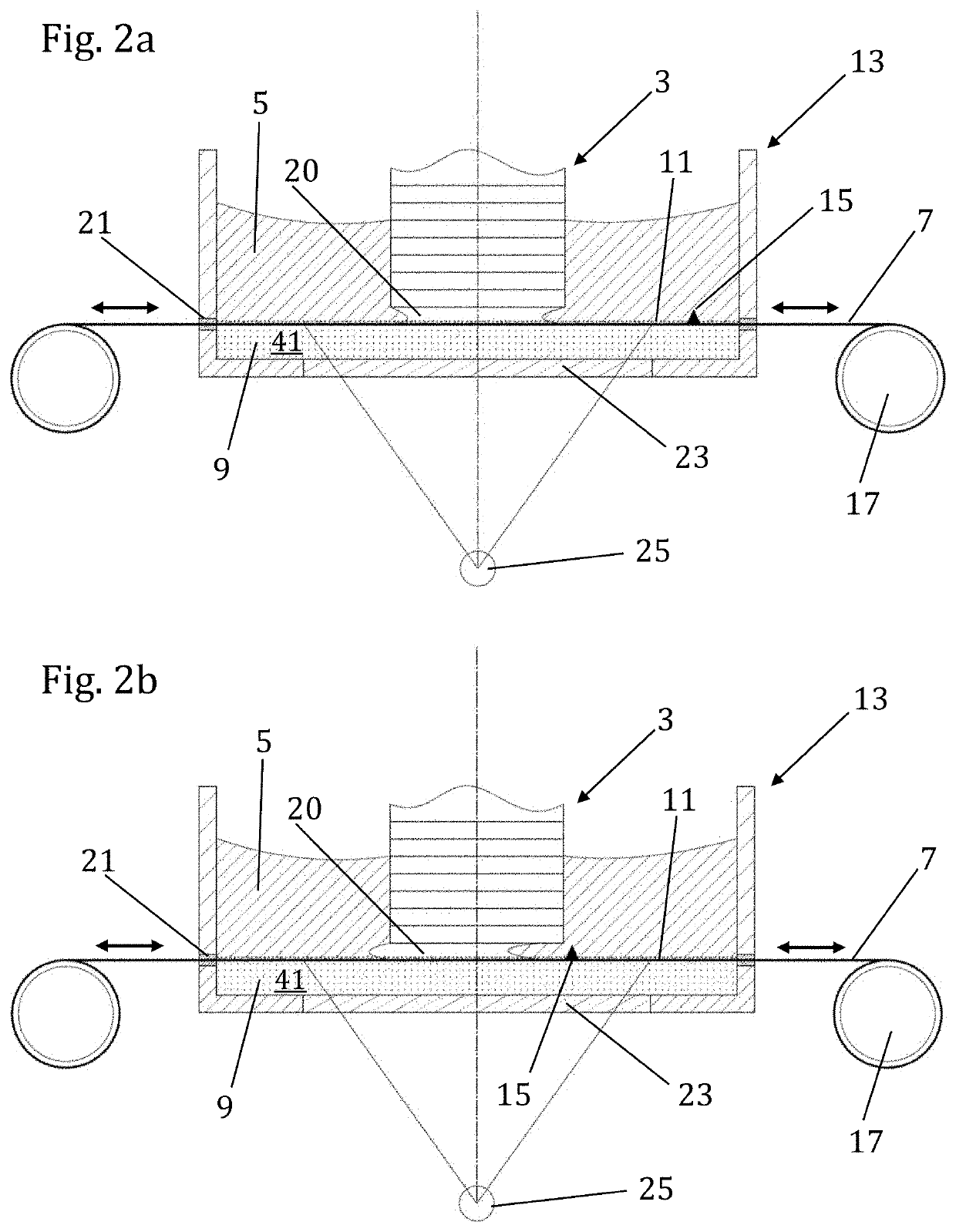
[0035]FIG. 1 shows a system 1 for generating, i.e. constructing, a three-dimensional component or body 3 by the so-called “rapid prototyping”. The body 3 can be created of individual layers 3i, wherein i=1, 2, 3 . . . , in a discontinuous or continuous manner from a photoreactive substance 5. The photoreactive substance 5 can be cured by a radiation with light, for instance UV light. In this regard, under the term “light” there is to be understood each kind of electromagnetic radiation which is suitable for curing the respective substance 5. The photoreactive substance 5 is for instance substantially “liquid”, wherein under this term also a paste-like consistency with a random viscosity is understood.

[0036]The photoreactive substance 5 is at least partly in contact with a semipermeable layer or ply 7 which, in turn, is at least partly in contact with a second phase 9. In this connection, under the term “phase” there are understood chemical compounds of any state of aggregation, i.e....


PUM

PropertyMeasurementUnit
Densityaaaaaaaaaa
Flexibilityaaaaaaaaaa
Shapeaaaaaaaaaa

Abstract

A system (1) for constructing a component, contains a trough (13) with an at least partly transparent base (23), an at least partly stretchable semipermeable layer (7), for receiving a photosensitive substance (5), and a phase (9) arranged below the semipermeable layer (7) and forms an intermediate layer (11) within the photosensitive substance (5). A light source (25) is below the trough base (23) for curing the photoreactive substance (5) in some regions. A construction platform (31) is above the semipermeable layer (7) and can be lifted and lowered for receiving the component (3), as well as with a driver (15) which extends from the semipermeable layer (7) in the direction of the construction platform (31) and can be moved relative to the trough base (23) to convey the photoreactive substance (5) into a gap (20) between the construction platform (31) and the semipermeable layer (7).

Description

[0001]This application is a National Stage Application of PCT / AT2017 / 060073, filed 23 Mar. 2017, which claims benefit of Serial No. A 50247 / 2016, filed 25 Mar. 2016 in Austria, and which applications are incorporated herein by reference. To the extent appropriate, a claim of priority is made to each of the above-disclosed applications.BACKGROUND OF THE INVENTION[0002]The invention relates in general to a stereolithography system for a continuous and / or non-continuous construction of a three-dimensional body in a layer-by-layer manner.[0003]More precisely, the invention relates to a system for constructing a component, containing a trough with an at least partly transparent base, an at least partly stretchable semipermeable layer for receiving a photosensitive substance, and a phase which is arranged below the semipermeable layer and which is able to form an intermediate layer within the photosensitive substance, a light source which is arranged below the trough base for curing the p...

Claims


Application Information

Patent Timeline
IPC IPC(8): B29C64/135B29C64/20B29C64/223B29C64/393B29C64/218B29C67/24B33Y10/00
CPCB29C64/135B29C64/20B29C64/218B29C64/223B29C64/393B29C67/244B33Y10/00B29C64/236B33Y30/00B33Y40/00B29C64/264B29C64/321B29C64/245B29C64/227B29C64/124
Inventor STADLMANN, KLAUS
Owner STADLMANN KLAUS
Why Eureka
Try Eureka