Vascular access

a technology of vascular access and vascular valve, which is applied in the direction of catheters, blood pumps, other medical devices, etc., can solve the problems of long time-consuming and laborious, blood reaction to foreign material residing in the blood stream, and less than optimal, and achieves the effect of simple procedur

Active Publication Date: 2021-11-23
ABIOMED EURO
View PDF19 Cites 0 Cited by
  • Summary
  • Abstract
  • Description
  • Claims
  • Application Information

AI Technical Summary

Benefits of technology

[0006]It is an objective of the present invention to provide devices for achieving access to large vessels or cavities, wherein the access allows the introduction and / or removal of large diameter devices, tissue or fluid through the access in a safe and controlled manner and by a simple procedure.
[0007]It is another objective of the present invention to provide a vascular graft that is easily secured to a vessel or cavity, provides hemostasis and allows the introduction or removal of large devices or material.
[0008]It is another objective of the present invention to provide a vascular graft equipped at its distal end with a hemostatic valve that allows the introduction or removal of large devices or material.

Problems solved by technology

Introducers that are used for more than 24 hours face the problem of blood reaction to foreign material residing in the blood stream for long duration.
The use of inappropriate devices, tools and procedures in peripheral vascular access has compromised the potential of peripheral vascular access and resulted in less than optimal results.
Once blood enters the graft, the porous Dacron mesh is penetrated and clogged by the blood.
Device introduction into these grafts requires physicians to innovate and experiment with different techniques and tools, leading to unpredictable results and high complication rates.
Any failure in hemostasis at any time, during or after device insertion, could lead to significant blood loss or even patient death.

Method used


Image

  • Vascular access
  • Vascular access
  • Vascular access

Examples


Embodiment Construction

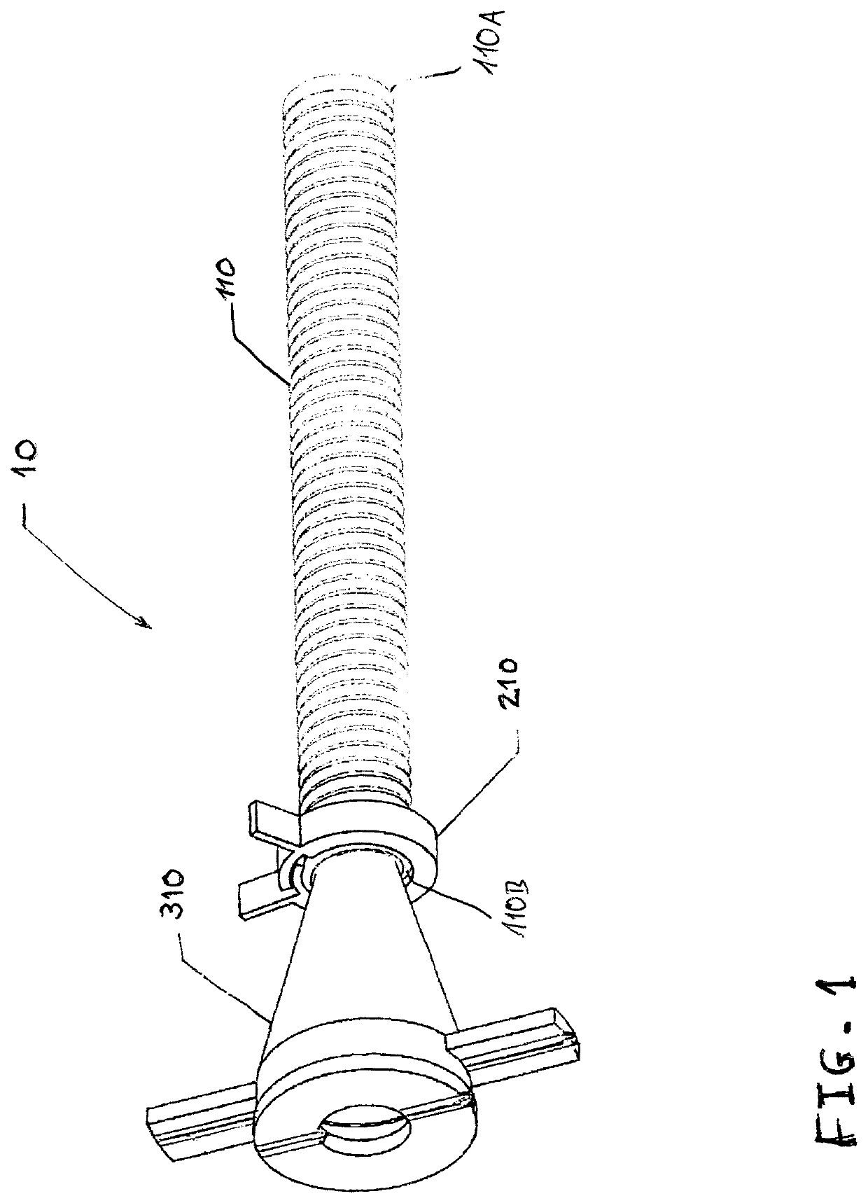
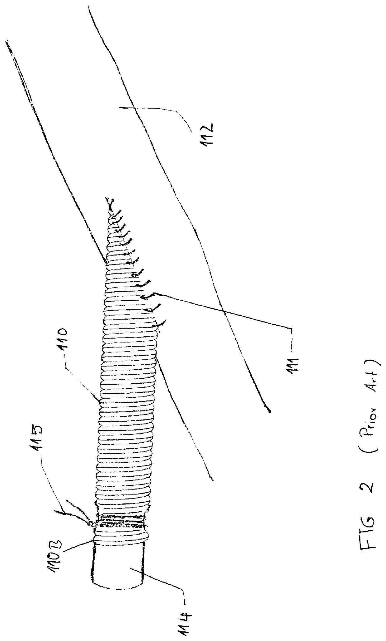
[0065]Referring to FIG. 1, a graft system 10 in accordance with the present invention is shown. The graft system 10 comprises a graft 110 having a proximal end 110A and a distal end 110B, a clamp 210 and a hemostasis valve 310. The graft 110 is typically a porous soft medical fabric as described in U.S. Pat. No. 3,953,566 and is intended for use as a conduit in contact with blood and biological tissue. The graft 110 is a commonly used medical product available in many different shapes, sizes and materials. The graft 110 is typically sutured to a vessel as shown in FIG. 2 wherein the graft 110 is secured to vessel 112 using surgical sutures 111. Sutures 111 are common medical products available in many different shapes, sizes and materials.

[0066]Typically, a graft 110 is used in a medical procedure that needs to gain access to a vessel in order to introduce and / or remove a medical product and / or devices, or to allow blood or bodily fluid to be circulated through the graft 110 to othe...


PUM


Abstract

A system for providing vascular access in a patient's body may comprise at least one hemostatic valve (610) and at least one clamp (210) to be used with a vascular graft (110). The vascular graft (110) comprises a tubular body having a proximal end (110A) and a distal end (110B), the proximal end (110A) being configured to be attached to a vessel in a patient's body. The at least one valve (610) is configured to be attached to the distal end (110B) of the graft's tubular body and comprises a housing (616) including a flexible membrane (611) that allows a medical device (810) to be inserted through the membrane (611) into said vascular graft (110). The valve (610) further comprises an introducer sheath (615) configured to be inserted into the distal end (110B) of the graft's tubular body. The at least one clamp (210) is configured to be disposed around the graft's tubular body and has a first configuration that allows insertion of the valve's introducer sheath (615) into the distal end (110B) of the graft's tubular body and a second configuration that allows clamping of the graft (110) against the valve's introducer sheath (615), when inserted in the graft's tubular body.

Description

CROSS-REFERENCE TO RELATED APPLICATIONS[0001]This application is a United States National Stage filing under 35 U.S.C. § 371 of International Application No. PCT / EP2015 / 075792, filed Oct. 2, 2015, which claims the benefit of European Patent Application No. 14187372, filed Oct. 7, 2014, the contents of all of which are incorporated by reference herein in their entirety. International Application No. PCT / EP2015 / 075792 published under PCT Article 21(2) in English.BACKGROUND[0002]Long term vascular access is a common medical procedure used in several medical situations including dialysis for patients requiring frequent dialysis treatments, chemotherapy treatment or ventricular assist device use. Different devices and different methods are used depending on patient needs. Long term vascular access in patients needing ventricular assist devices is common through an open chest procedure and direct cardiovascular access.[0003]Lately there has been a move toward the use of peripheral vessels...

Claims


Application Information

Patent Timeline
Patent Type & Authority Patents(United States)
IPC IPC(8): A61M39/06
CPCA61M39/0613A61M2039/0633A61M2039/0653A61M2039/0673A61M2039/0686A61M25/0097A61M25/06A61M25/0662A61M2039/0258A61M60/00A61B17/3415A61B2017/3419
Inventor FANTUZZI, GLENMRAZ, DIONRAESS, DANIEL A.BROUSSEAU, DAVID A.MAYO, SUSANNA
Owner ABIOMED EURO
Why Eureka
Try Eureka