
Precision system for additive fabrication

a technology of additive fabrication and precision system, which is applied in the direction of manufacturing tools, applying layer means, manufacturing driving means, etc., can solve the problems of inability to planarize the composition is not suitable for additive fabrication use with inkjet printers, and the inability to perform the planarization of the deposited uv curable cationic ink, etc., to achieve the effect of improving the material properties of an accurate obj

Active Publication Date: 2021-11-16
INKBIT LLC
View PDF44 Cites 1 Cited by
  • Summary
  • Abstract
  • Description
  • Claims
  • Application Information

AI Technical Summary

Benefits of technology

The invention aims to improve the material properties of objects made using an additive process with an inkjet printer. It includes an optical feedback scanner and a controller to control the emission of material from the printer jets according to the optical feedback of the jetted ink. The ink also contains a UV curable cationic compound and may include an optical enhancement component to improve the ability of the scanner to accurately sense the surface and / or body properties of the emitted material. Additionally, the method includes depositing particles that enhance the mechanical, thermal, and / or optical properties of the photo-curable material. Lastly, heating the printing platform or chamber speeds up curing of the photo-curable material.

Problems solved by technology

However, such compositions are ill-suited for being used with ink jet printers for additive fabrication.
Although slow curing may be acceptable for 2D inkjet printing, it is not compatible with certain addition processes performed with today's inkjet printers.
Indeed, given its slow curing, a planarization of the deposited UV curable cationic ink cannot be performed without leading to defects of the manufacture objects, low precision, or fouling of the printer.
For example, mechanical surface control using rollers or planarizers may not be feasible because of the non-fully-cured state of the surface at the time such surface control would have to be performed.
UV curable cationic inks, as is the case with other fabrication materials suitable for jetted additive fabrication, are not directly suitable for optical scanning as inadequate optical signal strength may propagate from the material during scanning.

Method used


Image

  • Precision system for additive fabrication
  • Precision system for additive fabrication
  • Precision system for additive fabrication

Examples


Embodiment Construction

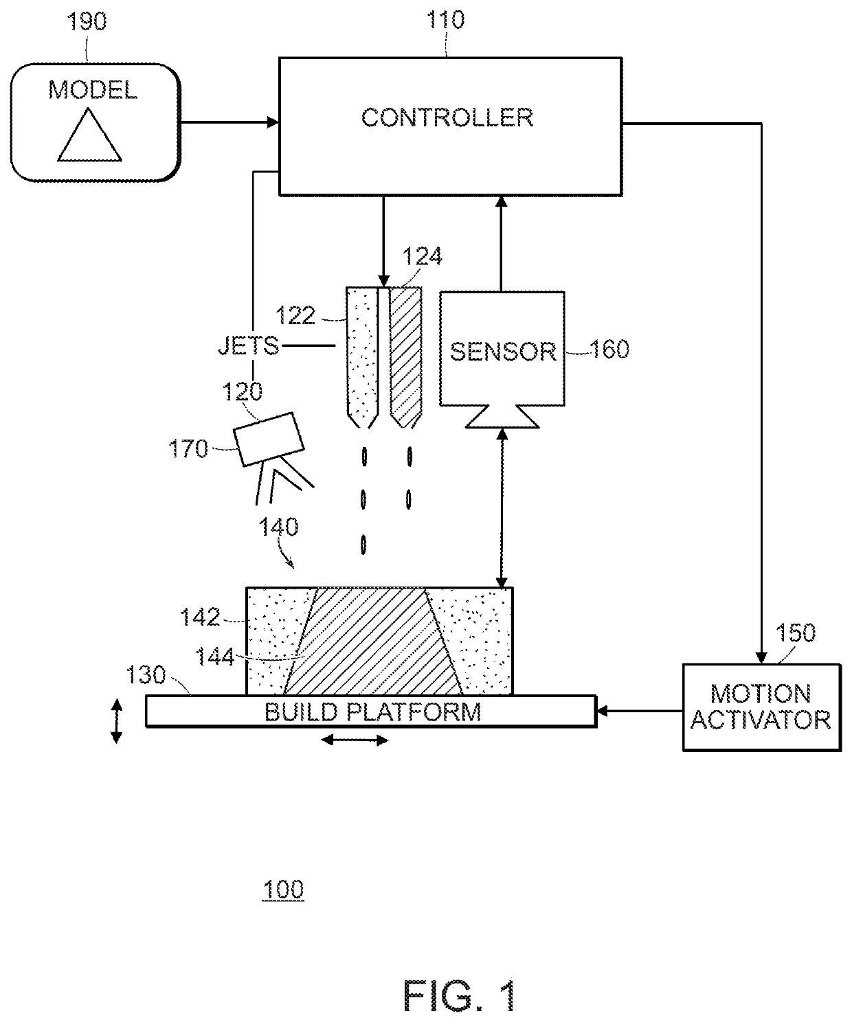
[0045]The description below relates additive fabrication, for example using a jetting-based 3D printer 100 shown in FIG. 1. The printer 100 uses jets 120 (inkjets) to emit material for deposition on a partially fabricated objected layers. In the printer illustrated in FIG. 1, the object is fabricated on a build platform, which is controlled to move related to the jets is a raster-like pattern to form successive layers, and in this example also to move relative to the jets to maintain a desired separation of the jets and the surface of the partially-fabricated object. As illustrated, there are multiple jets 122, 124, with one jet 122 being used to emit a support material to form a support structure 142 of the object, and another jet 124 being used to emit built material to form the object 144 itself. For materials for which curing is triggered by an excitation signal, such as an ultraviolet illumination, a curing signal generator 170 (e.g., a UV lamp) triggers curing of the material ...


PUM

PropertyMeasurementUnit
sizeaaaaaaaaaa
temperatureaaaaaaaaaa
surface tensionaaaaaaaaaa

Abstract

An approach to precision additive fabrication uses jetting of cationic compositions in conjunction with a non-contact (e.g., optical) feedback approach. By not requiring contact to control the surface geometry of the object being manufactured, the approach is tolerant of the relative slow curing of the cationic composition, while maintaining the benefit of control of the deposition processes according to feedback during the fabrication processes. This approach provides a way to manufacture precision objects and benefit from material properties of the fabricated objects, for example, with isotropic properties, which may be at least partially a result of the slow curing, and flexible structures, which may not be attainable using conventional jetted acrylates.

Description

CROSS-REFERENCE TO RELATED APPLICATIONS[0001]This application is a continuation of International Application No. PCT / US2019 / 65436 filed on Dec. 10, 2019, which claims the benefit of U.S. Provisional Application No. 62 / 777,422, filed on Dec. 10, 2018, the contents of all of which are hereby incorporated by reference in their entireties.BACKGROUND OF THE INVENTION[0002]This invention relates to the precision methods and systems used in additive fabrication.[0003]Additive manufacturing, also referred to as 3D printing, refers to a relatively wide class of techniques for producing parts according to a computer-controlled process, generally to match a desired 3D specification, for example, a solid model. A number of different classes of materials have been used for such 3D printing, with different materials providing corresponding advantages and / disadvantages for different fabrication techniques. For example, a survey of materials may be found in Ligon et al. “Polymers for 3D printing an...

Claims


Application Information

Patent Timeline
Patent Type & Authority Patents(United States)
IPC IPC(8): B29C64/393B29C64/112B29C64/209B33Y10/00B33Y30/00B33Y70/00C09D11/101C09D11/102C09D11/38B33Y50/02B29C64/364B29K63/00
CPCB29C64/393B29C64/112B29C64/209B33Y10/00B33Y30/00B33Y50/02B33Y70/00C09D11/101C09D11/102C09D11/38B29C64/364B29K2063/00B29C64/227
Inventor WANG, WENSHOUELLSON, GREGORYZHANG, YANCHEN, DESAIRAMOS, JAVIERMATUSIK, WOJCIECHVIDIMCE, KIRIL
Owner INKBIT LLC
Learn More