Modular battery configured for wire bonding

a module battery and wire bonding technology, applied in secondary cells, battery components, battery service/maintenance, etc., can solve the problems of battery pack contributing to the high cost of electrical vehicles, conventional soldering and welding process, and battery pack design not being adapted for mass assembly and production, etc., to achieve high quality, high performance, and without any negative impact on production throughput

Active Publication Date: 2021-11-02
XOS INC
View PDF45 Cites 0 Cited by
  • Summary
  • Abstract
  • Description
  • Claims
  • Application Information

AI Technical Summary

Benefits of technology

The battery modules described in this patent offer several advantages over conventional battery packs. These modules use wire bonding technology, which provides high performance and quality monitoring while avoiding the need for post-cleaning residue. The modules have openings that allow for efficient wire bonding and minimize exposed areas of battery cells. The technology also allows for connection between the battery cells and voltage sensing PCBs, which improves battery performance and reduces costs. Overall, the wire bonding technology improves battery performance and reduces the cost of battery packs, making it more efficient for various applications, such as electric vehicles and energy storage.

Problems solved by technology

One of the key challenges of electric vehicles is the battery pack design.
However, the conventional battery pack design is not adapted for mass assembly and production.
The manual assembly and production of the battery pack contributes to the high cost of electrical vehicles.
One of the problems of battery packs is the conventional soldering and welding process.
The conventional soldering and welding process has several drawbacks, such as an undesirable time requirement, induced thermal stresses, required post-process cleaning, minimal flexibility, and poor quality control and monitoring.

Method used


Image

  • Modular battery configured for wire bonding
  • Modular battery configured for wire bonding
  • Modular battery configured for wire bonding

Examples


Embodiment Construction

[0053]The detailed description set forth below in connection with the appended drawings is intended as a description of various configurations and is not intended to represent the only configurations in which the concepts described herein may be practiced. The detailed description includes specific details for the purpose of providing a thorough understanding of various concepts. However, it will be apparent to those skilled in the art that these concepts may be practiced without these specific details.

[0054]Several aspects of electric batteries, battery packs, battery modules, and modular sub-components of battery modules will now be presented with reference to various examples.

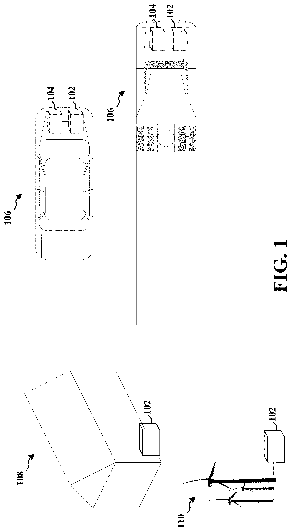
[0055]FIG. 1 illustrates examples of systems that may include an electric battery pack 102 in accordance with the aspects presented herein. The battery pack may be comprised in an energy storage system for commercial and / or residential buildings 108. Energy storage systems may be used to store energy for uti...


PUM

PropertyMeasurementUnit
lengthaaaaaaaaaa
lengthaaaaaaaaaa
heightaaaaaaaaaa

Abstract

Aspects of a modular clip for an electric battery module, a battery module comprising multiple such modular clips, and a battery pack comprising multiple battery modules are provided. The modular clip includes a housing configured to receive a plurality of battery cells. The modular clip may further comprise at least one interconnect plate. The modular clip may further comprise a retainer plate including a plurality of top cell recesses, each of the plurality of top cell recesses may comprise an opening to enable wire bonds between electrical terminals of a battery cell and the at least one interconnect plate. The battery module may comprise a plurality of wire bonds between at least one voltage sensing PCB and the at least one interconnect plate.

Description

CROSS-REFERENCE TO RELATED APPLICATIONS[0001]This application is a continuation of U.S. application Ser. No. 15 / 948,820, entitled “Modular Battery Configured for Wire Bonding” and filed on Apr. 9, 2018, which claims the benefit of U.S. Provisional Application Ser. No. 62 / 626,050, entitled “Modular Battery Configured for Wire Bonding” and filed on Feb. 3, 2018; and is a continuation-in-part of U.S. application Ser. No. 15 / 948,451, entitled “Modular Battery” and filed on Apr. 9, 2018, which the benefit of U.S. Provisional Application Ser. No. 62 / 626,042, entitled “Modular Battery” and filed on Feb. 3, 2018, the entire contents of each of which are expressly incorporated by reference herein in their entirety.BACKGROUNDField[0002]Aspects of the present disclosure relate generally to an electric battery module and an electric battery pack with modular design. Specifically, aspects of the present disclosure relate to an electric battery module configured for wire bonding.Description of th...

Claims


Application Information

Patent Timeline
Patent Type & Authority Patents(United States)
IPC IPC(8): H01M50/207H01M50/204H01M50/20H01M50/148H01M50/147H01M50/502H01M10/42H01M10/48H01M50/213H01M50/262H01M50/503H01M50/519H01M50/528H01M50/529H01M50/569
CPCH01M50/20H01M10/425H01M10/482H01M50/502H01M2010/4271H01M2220/20Y02E60/10H01M50/519H01M50/213H01M50/569H01M50/503H01M50/262
Inventor HARRIS, III, JOHN HENRY
Owner XOS INC
Why Eureka
Try Eureka