
Backlight module and method of manufacturing same

a backlight module and backlight technology, applied in the field of backlight modules, can solve the problems of low light-emitting efficiency and low brightness of current surface light sources, no better way to solve these problems, and the application of surface light sources, so as to improve the overall illuminating performance of a surface light source, improve the overall uniformity of the surface light source, and increase the area ration

Active Publication Date: 2021-10-26
WUHAN CHINA STAR OPTOELECTRONICS TECH CO LTD
View PDF16 Cites 0 Cited by
  • Summary
  • Abstract
  • Description
  • Claims
  • Application Information

AI Technical Summary

Benefits of technology

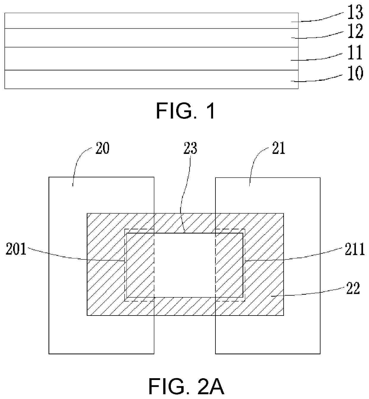
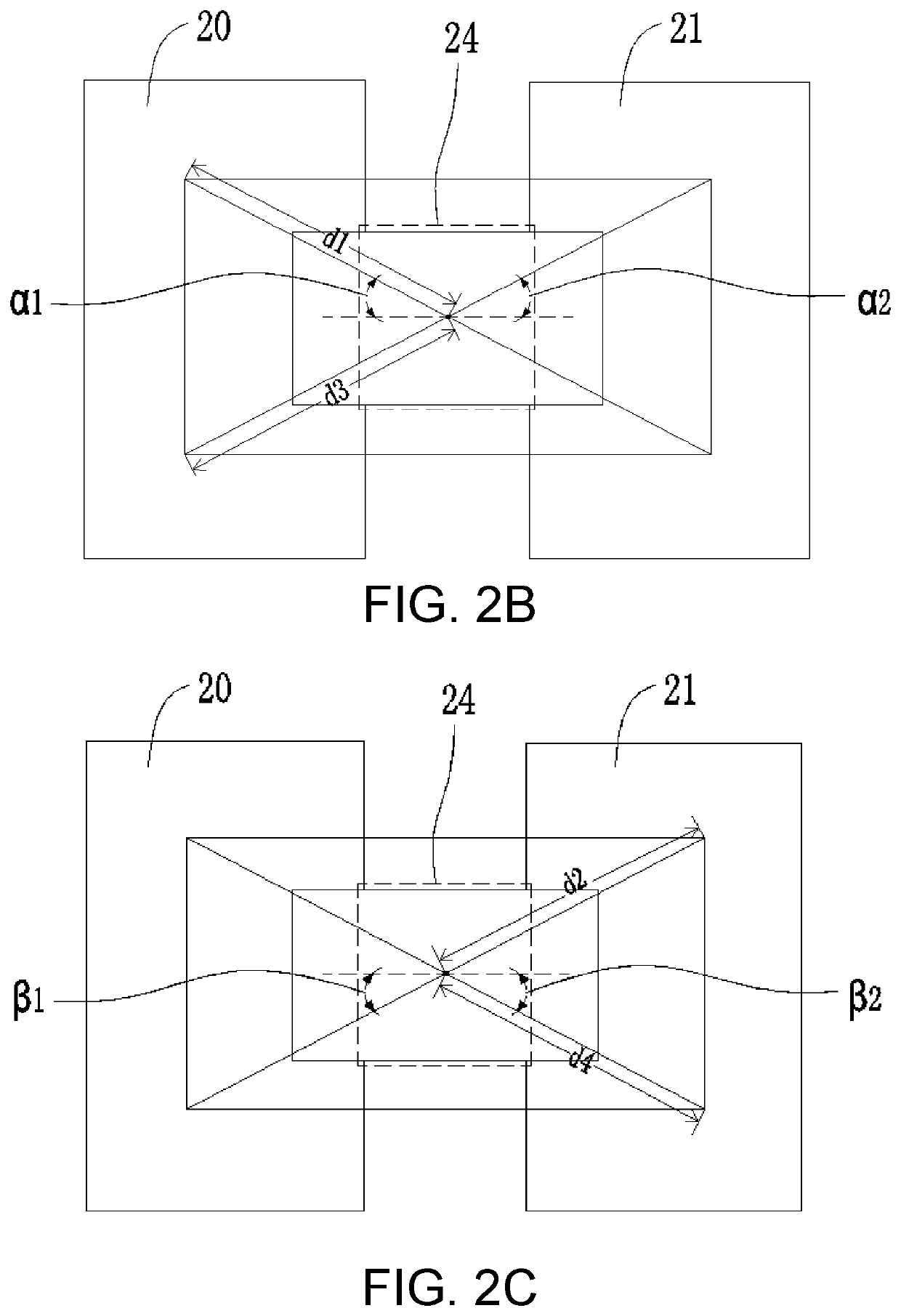
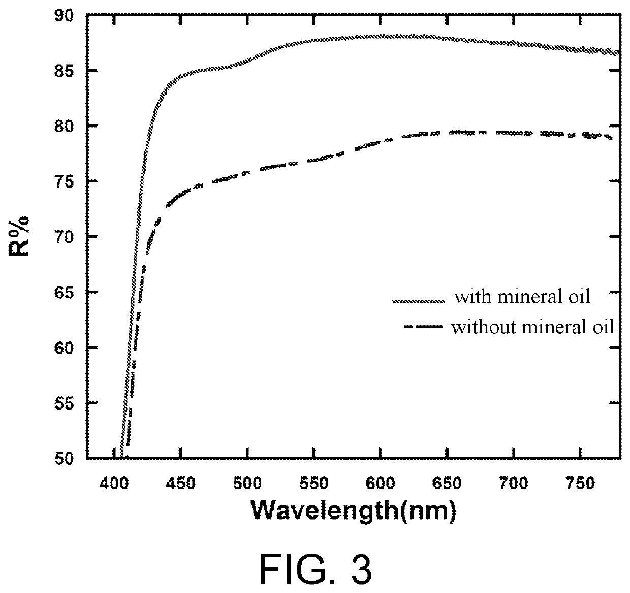
The present disclosure provides a backlight module and a method of manufacturing same, which can increase the area ratio of a mineral oil layer on a flexible substrate, ensure the size and tolerance of a window opening region of the mineral oil layer, and improve the illuminating performance of a surface light source. Compared with a current backlight module, the invention reduces the area of the window opening region of the mineral oil layer and increases the area ratio of the mineral oil layer on the substrate, ensuring the same pad size on two sides of the opening window region of the mineral oil layer. This improves the reflectivity of the entire surface of the substrate and helps ensure an overall uniformity of the surface light source.

Problems solved by technology

However, due to reflectivity limitations of a plate having mineral oil and area limitations of a window opening region of the plate having the mineral oil, current surface light sources have low light-emitting efficiency and low brightness.
Due to heat resistance issues of other film layers, applications of the surface light sources have been limited, and there is no better way to solve these issues.
Therefore, current technologies have drawbacks and need to be improved.

Method used


Image

  • Backlight module and method of manufacturing same
  • Backlight module and method of manufacturing same
  • Backlight module and method of manufacturing same

Examples


Embodiment Construction

[0032]The embodiments described herein with reference to the accompanying drawings are explanatory, illustrative, and used to generally understand the present disclosure. Furthermore, directional terms described by the present disclosure, such as top, bottom, front, back, left, right, inner, outer, side, etc., are only directions by referring to the accompanying drawings, and thus the used terms are used only for the purpose of describing embodiments of the present disclosure and are not intended to be limiting of the present disclosure. In the drawings, modules with similar structures are labeled with the same reference number.

[0033]The present disclosure provides a backlight module to address technical problems and solves drawbacks of current backlight modules that there are limitations of a reflectivity of a substrate having mineral oil and an area of a window opening region of the substrate having the mineral oil, such that current surface light sources have low light-emitting e...


PUM

PropertyMeasurementUnit
sizeaaaaaaaaaa
thicknessaaaaaaaaaa
thicknessaaaaaaaaaa

Abstract

A backlight module and a method of manufacturing same are provided. The backlight module includes a flexible circuit substrate. The flexible circuit substrate includes a flexible substrate, a first pad, a second pad, a mineral oil layer, and a light emitting diode (LED) chip. The first pad and the second pad are disposed on the flexible substrate. The mineral oil layer is disposed on the flexible substrate and is patterned to form a window opening region. Two ends of the LED chip are electrically connected to a positive electrode of the first pad and a negative electrode of the second pad respectively through the window opening region. The window opening region exposes at least the positive electrode and the negative electrode.

Description

FIELD OF INVENTION[0001]The present disclosure relates to the field of liquid crystal display technologies, and more particularly to a backlight module and a method of manufacturing same.BACKGROUND OF INVENTION[0002]Sub-millimeter light emitting diodes (surface light sources) are now a hotspot in the market and have many advantages such as light weight, power savings, being flexible and foldable, high brightness, making wide-screen display devices with narrow bezels, and making display devices with high dynamic contrast (HDR). Therefore, the sub-millimeter light emitting diodes have become a focus of market attention. However, due to reflectivity limitations of a plate having mineral oil and area limitations of a window opening region of the plate having the mineral oil, current surface light sources have low light-emitting efficiency and low brightness. Due to heat resistance issues of other film layers, applications of the surface light sources have been limited, and there is no b...

Claims


Application Information

Patent Timeline
Patent Type & Authority Patents(United States)
IPC IPC(8): F21V23/00F21V33/00F21S4/22F21K9/90F21Y115/10
CPCF21V33/0052F21K9/90F21S4/22F21Y2115/10H01L27/1214H01L27/124H01L27/1259G02F1/1336G02F1/133603G02F1/133606
Inventor YANG, YONG
Owner WUHAN CHINA STAR OPTOELECTRONICS TECH CO LTD
Learn More