
Organic electroluminescent element

a technology of electroluminescent elements and organic materials, which is applied in the field of organic electroluminescent elements, can solve the problems that the combination other than the above combination has not been specifically verified, and achieve the effects of optimum light emission characteristics, excellent light emission efficiency, and good balance of performan

Active Publication Date: 2021-10-05
SK MATERIALS JNC CO LTD +1
View PDF9 Cites 0 Cited by
  • Summary
  • Abstract
  • Description
  • Claims
  • Application Information

AI Technical Summary

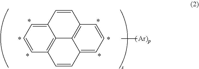
Benefits of technology

[0011]As a result of intensive studies to solve the above problems, the present inventors have found that an excellent organic EL element can be obtained by disposing a light emitting layer containing a polycyclic aromatic compound having a plurality of aromatic rings linked with a boron atom and a nitrogen atom or an oxygen atom and a specific pyrene-based compound between a pair of electrodes to constitute an organic EL element, and have completed the present invention.
[0012]According to a preferable embodiment of the present invention, it is possible to provide a compound represented by formula (1) and a compound represented by formula (2), capable of obtaining optimum light emitting characteristics in combination with the compound represented by formula (1) By manufacturing an organic EL element using a material for a light emitting layer obtained by combining these compounds, it is possible to provide an organic EL element that is excellent in at least one of chromaticity, driving voltage, and quantum efficiency.
[0081]According to a preferable embodiment of the present invention, it is possible to provide a polycyclic aromatic compound represented by formula (1) and a pyrene-based compound represented by formula (2), capable of obtaining optimum light emitting characteristics in combination with the polycyclic aromatic compound represented by formula (1). By manufacturing an organic EL element using a material for a light emitting layer obtained by combining these compounds, it is possible to provide an organic EL element particularly having excellent light emission efficiency and exhibiting well-balanced performance.
[0082]Furthermore, by introducing a cycloalkyl group into the compound of the above general formula (1) and a multimer thereof, reduction in melting point and sublimation temperature thereof can be expected. This means that thermal decomposition of a material and the like can be avoided because purification can be performed at a relatively low temperature in sublimation purification that is almost indispensable as a method for purifying a material for an organic device requiring high purity, such as an organic EL element. This also applies to a vacuum vapor deposition process which is a powerful means for manufacturing an organic device such as an organic EL element, and the process can be performed at a relatively low temperature. Therefore, thermal decomposition of a material can be avoided. As a result, a high performance organic device can be obtained. Furthermore, many of the above multimers have high sublimation temperatures due to high molecular weight, high planarity, and the like. Therefore, reduction in sublimation temperature by introduction of a cycloalkyl group is more effective. Furthermore, solubility in an organic solvent is improved by the introduction of a cycloalkyl group. Therefore, application to manufacturing an element using a coating process is also possible. In addition, concentration quenching can be suppressed by introducing a substituent having a large size, such as a cycloalkyl. However, the present invention is not particularly limited to these principles.

Problems solved by technology

However, a combination other than the above combination has not been specifically verified.

Method used


Image

  • Organic electroluminescent element
  • Organic electroluminescent element
  • Organic electroluminescent element

Examples


example 1

Element Including Compound (2-1) as Host and Compound (1-139) as Dopant

[0526]A glass substrate (manufactured by Opto Science, Inc.) having a size of 26 mm×28 mm×0.7 mm, obtained by forming a film of ITO having a thickness of 180 nm by sputtering and polishing the ITO film to 150 nm, was used as a transparent supporting substrate. This transparent supporting substrate was fixed to a substrate holder of a commercially available vapor deposition apparatus (manufactured by Showa Shinku Co., Ltd.). Molybdenum vapor deposition boats containing HI, HAT-CN, HT-1, HT-2, compound (2-1), compound (1-139), ET-1, and ET-2, respectively, and aluminum nitride vapor deposition boats containing Liq, magnesium, and silver, respectively, were mounted thereon.

[0527]Layers as described below were formed sequentially on the ITO film of the transparent supporting substrate. A vacuum chamber was depressurized to 5×10⁻⁴ Pa. First, HI was heated, and vapor deposition was performed so as to obtain a film thic...


PUM

PropertyMeasurementUnit
thicknessaaaaaaaaaa
thicknessaaaaaaaaaa
thicknessaaaaaaaaaa

Abstract

By manufacturing an organic EL element using a material for a light emitting layer including a pyrene-based compound represented by the following formula (2) as a host material and a polycyclic aromatic compound in which a plurality of aromatic rings is linked with a boron atom and a nitrogen atom or an oxygen atom as a dopant material, an organic EL element having, for example, excellent light emission efficiency is provided.In the above formula (2), at least one hydrogen atom in a pyrene moiety may be substituted by an aryl having 6 to 10 carbon atoms or the like. Ar represents an aryl having 14 to 40 carbon atoms or a heteroaryl having 12 to 40 carbon atoms. These groups may be substituted by an aryl having 6 to 10 carbon atoms or the like. s and p each independently represent an integer of 1 or 2. s and p do not simultaneously represent 2. One or more hydrogen atoms in a compound represented by formula (2) may be each independently substituted by a halogen atom, cyano, or a deuterium atom.

Description

BACKGROUNDTechnical Field[0001]The present invention relates to an organic electroluminescent element having a light emitting layer containing a polycyclic aromatic compound as a dopant material and a specific pyrene compound as a host material, and a display apparatus and a lighting apparatus using the same.Related Art[0002]Conventionally, a display apparatus employing a luminescent element that is electroluminescent can be subjected to reduction of power consumption and thickness reduction, and therefore various studies have been conducted thereon. Furthermore, an organic electroluminescent element (hereinafter, referred to as an organic EL element) formed from an organic material has been studied actively because weight reduction or size expansion can be easily achieved. Particularly, active studies have been hitherto conducted on development of an organic material having light emitting characteristics for blue light which is one of the primary colors of light, or the like, and a...

Claims


Application Information

Patent Timeline
Patent Type & Authority Patents(United States)
IPC IPC(8): H01L51/00H01L51/52H01L51/50C07D209/82C07D333/52C07D307/78
CPCH01L51/0074H01L51/008H01L51/0054H01L51/0058H01L51/0059H01L51/0072H01L51/0073H01L51/0077H01L51/5092H01L51/5206H01L51/5221C07D209/82C07D307/78C07D333/52H01L51/5012H01L51/5056H01L51/5072H10K85/622H10K85/626H10K85/631H10K85/322H10K85/6574H10K50/11H10K85/6576H10K50/81H10K50/82H10K50/171H10K85/30H10K85/6572H10K50/15H10K50/16
Inventor HATAKEYAMA, TAKUJIYAMAGA, YUKOBABA, DAISUKESHIREN, KAZUSHI
Owner SK MATERIALS JNC CO LTD
Learn More