Eureka AIR delivers breakthrough ideas for toughest innovation challenges, trusted by R&D personnel around the world.

Antenna and antenna module

a technology of antenna module and antenna, which is applied in the direction of antenna, antenna details, antenna earthing, etc., can solve the problems of difficult handling of antennas, unsuitable for provisioning in portable devices, and large size of antennas, and achieve satisfactory directivity and easy handling

Active Publication Date: 2021-09-28
FUJITSU COMPONENENT LTD
View PDF9 Cites 0 Cited by
  • Summary
  • Abstract
  • Description
  • Claims
  • Application Information

AI Technical Summary

Benefits of technology

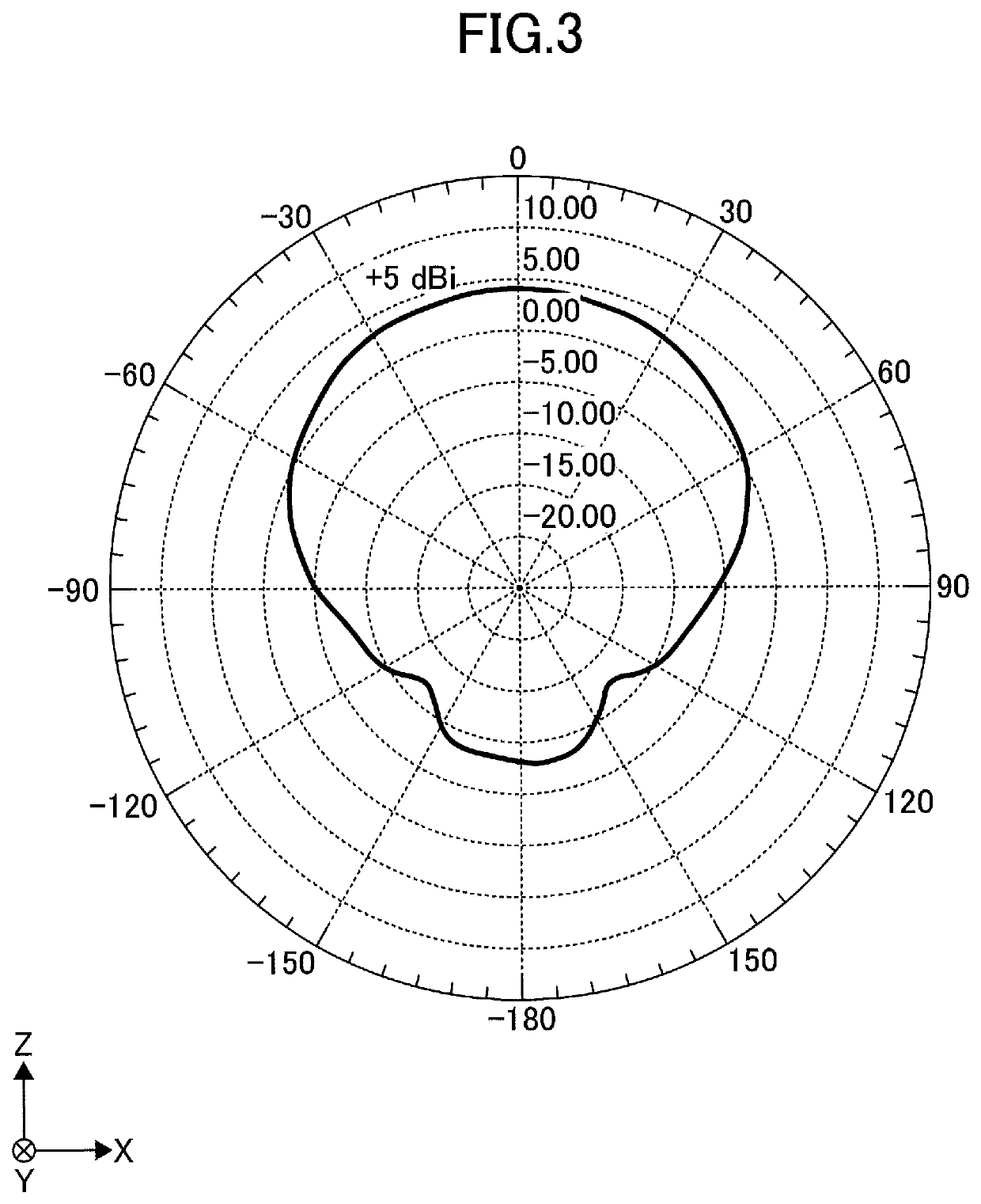
[0007]According to at least one embodiment, a small antenna having such a shape that is easy to handle and having a satisfactory directivity is provided.

Problems solved by technology

An antenna having a complex shape and a large size is not easy to handle, and is not suitable for provision in a portable device.

Method used


Image

  • Antenna and antenna module
  • Antenna and antenna module
  • Antenna and antenna module

Examples


Embodiment Construction

[0020]In the following, embodiments for implementing the invention will be described. The same members or the like are referred to by the same numerals, and a description thereof will be omitted.

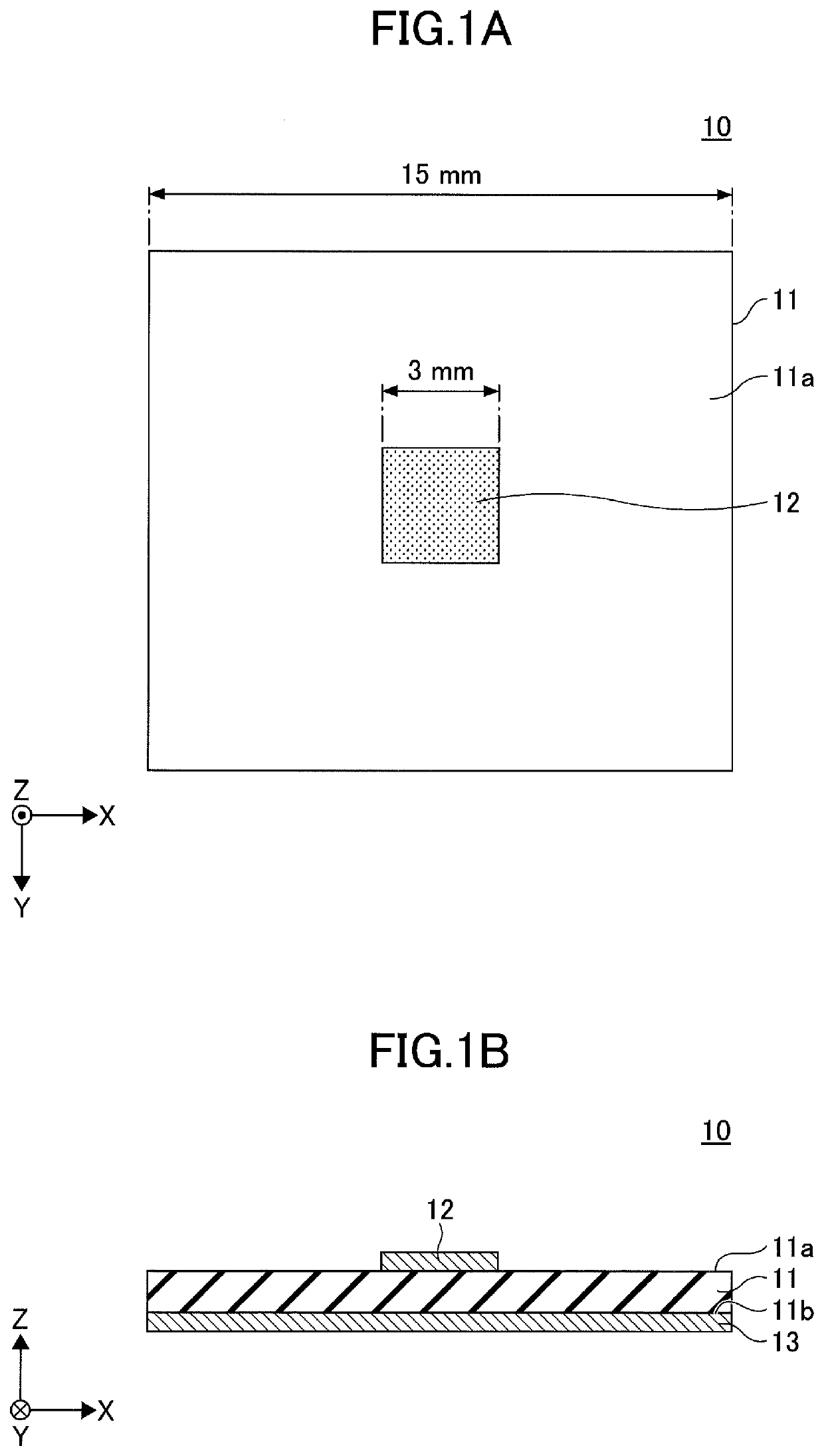
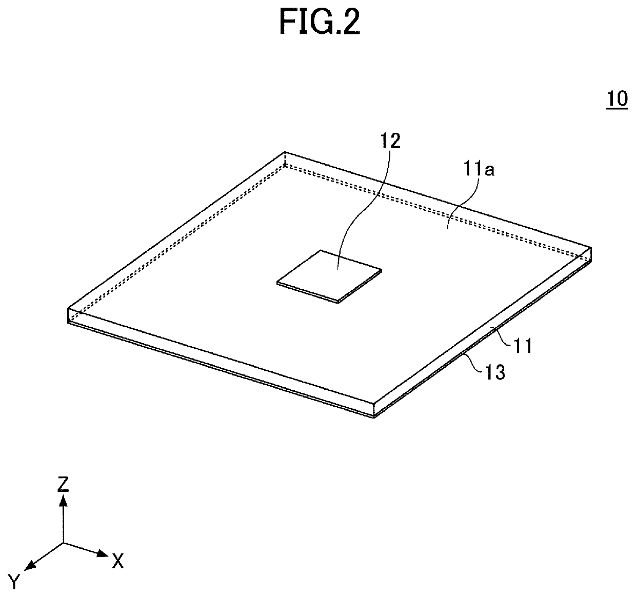
[0021]In the following, a patch antenna 10 will be described. FIG. 1A is a top view of the patch antenna 10. FIG. 1B is a cross-sectional view of the patch antenna 10. FIG. 2 is an axonometric view of the patch antenna 10.

[0022]The patch antenna 10 includes an insulating dielectric substrate 11, an antenna element 12 disposed on a surface 11a of the dielectric substrate 11, and a ground element 13 disposed on a surface 11b of the dielectric substrate 11. The antenna element 12 and the ground element 13 are metal films that are electrically conductive. The ground element 13 is coupled to a ground potential. The antenna element 12, which receives a feed power, serves as a radiation plane for radiating radio waves.

[0023]The dielectric substrate 11 is a square plate with a side of 15 mm and a th...


PUM


Abstract

An antenna includes a dielectric substrate, an antenna element formed on a first surface of the dielectric substrate, a ground element formed on a second surface of the dielectric substrate, and a metal conductor plate disposed over, and at a spaced distance from, the first surface of the dielectric substrate, the metal conductor plate being larger than the ground element.

Description

BACKGROUND OF THE INVENTION1. Field of the Invention[0001]The disclosures herein relate to an antenna and an antenna module.2. Description of the Related Art[0002]Antennas for transmitting and receiving radio waves are used in wireless communication. There are needs for an antenna capable of transmitting radio waves over as large a distance as possible and an antenna capable of receiving weak radio waves.[0003]An antenna is required to have not only an increased gain but also an improved directivity in order to transmit radio waves over as large a distance as possible and to receive weak radio waves. An antenna having a complex shape and a large size is not easy to handle, and is not suitable for provision in a portable device.[0004]There is a certain type of antenna module in which an antenna is connected to an electronic circuit for generating radio waves to be transmitted from the antenna and connected to a signal processing circuit for processing radio wave signals received by t...

Claims


Application Information

Patent Timeline
Patent Type & Authority Patents(United States)
IPC IPC(8): H01Q9/04H01Q1/48H01Q1/22H01Q19/10
CPCH01Q9/0407H01Q1/48H01Q19/104H01Q1/2283
Inventor YANAGI, MASAHIRO
Owner FUJITSU COMPONENENT LTD
Why Eureka
Eureka Blog
Learn More