
Plasma processing method and plasma processing apparatus

a plasma processing and plasma technology, applied in the field of plasma processing methods and plasma processing apparatuses, can solve the problems of difficult filling trenches and spaces with films, difficult mld filling, and difficult mld filling, etc., and achieves uniformity of coverage performance, high plasma controllability, and convenient uniform film thickness.

Active Publication Date: 2021-09-14
TOKYO ELECTRON LTD
View PDF10 Cites 0 Cited by
  • Summary
  • Abstract
  • Description
  • Claims
  • Application Information

AI Technical Summary

Benefits of technology

The method achieves improved uniformity in film thickness and quality across the substrate surface by optimizing plasma distribution, reducing voids and defects, and enhancing the modification effect, particularly in areas with high angular velocity disparities.

Problems solved by technology

However, along with miniaturization of circuit patterns, for example, as aspect ratios of trenches in trench and device isolation structures and spaces in line and space patterns increase, filling the trenches and the spaces with a film is sometimes difficult even in MLD.
On this occasion, an etching gas (or an etching solution) is liable to go into the opening, thereby causing contamination, and a metal is liable to go into the void in the following metallization, thereby generating a defect.
Such a problem can occur in not only ALD but also CVD (Chemical Vapor Deposition).
However, the film deposition method as described in Japanese Laid-Open Patent Application Publication No. 2013-135154 in which the distribution of OH groups is controlled by plasma and thereby controlling an amount of adsorption of the organic aminosilane gas is often more difficult to acquire preferable uniformity across the substrate than the film deposition method of causing one layer of a source gas on a substrate, oxidizing the one layer of the source gas, and modifying the one oxidized layer.
When a turntable type substrate processing apparatus or plasma processing apparatus is used, in the control of the distribution of OH groups by the plasma source, oxidation is likely to be insufficient at the periphery and many OH groups are likely to be present at the periphery because the peripheral portion rotates and moves faster than the central portion around the axis due to a difference in angular velocity.
Moreover, in other types of substrate processes and plasma processes that do not control the OH groups, with respect to the turntable type plasma processing apparatus, a supply of plasma at the periphery is likely to be lower than the supply at the central portion due to the above-mentioned difference in angular velocity, and a disproportion of the plasma process between the central portion and the peripheral portion of the turntable is liable to be generated.

Method used


Image

  • Plasma processing method and plasma processing apparatus
  • Plasma processing method and plasma processing apparatus
  • Plasma processing method and plasma processing apparatus

Examples


Embodiment Construction

[0044]Embodiments of the present invention are described below with reference to the accompanying drawings.

[0045][Configuration of Plasma Processing Apparatus]

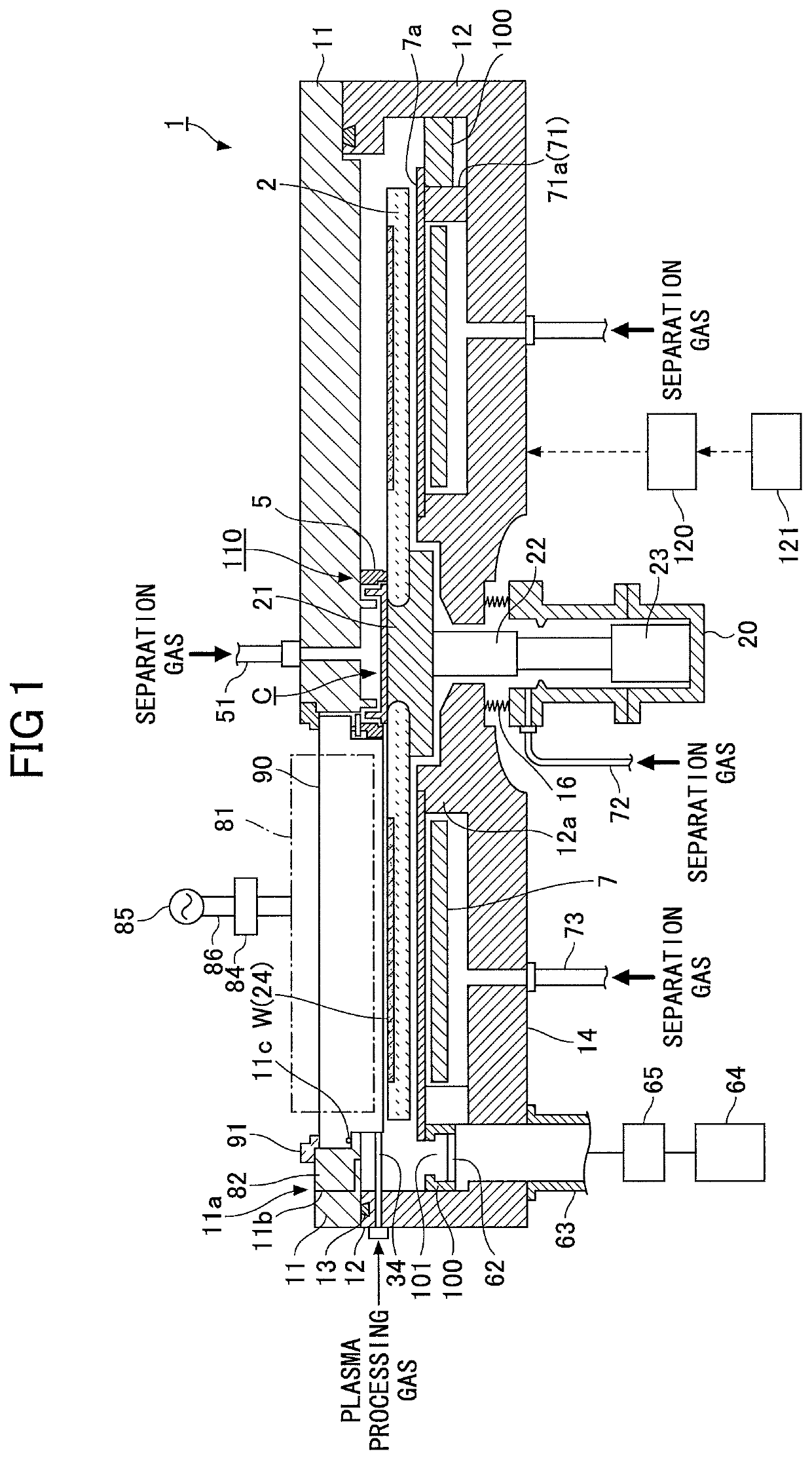
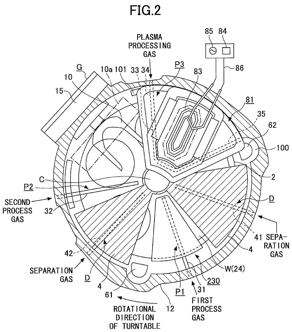
[0046]FIG. 1 is a schematic vertical cross-sectional view illustrating an example of a plasma processing apparatus according to an embodiment of the present invention. FIG. 2 is a schematic plan view illustrating an example of the plasma processing apparatus according to the embodiment. In FIG. 2, for convenience of explanation, a depiction of a top plate 11 is omitted.

[0047]As illustrated in FIG. 1, the plasma processing apparatus of the embodiment includes a vacuum chamber 1 having a substantially circular planar shape, and a turntable 2 that is disposed in the vacuum chamber 1 such that the rotational center of the turntable 2 coincides with the center of the vacuum chamber 1. The turntable 2 rotates wafers W placed thereon by rotating around its rotational center.

[0048]The vacuum chamber 1 is a process chamber to accommoda...


PUM

PropertyMeasurementUnit
widthaaaaaaaaaa
diameteraaaaaaaaaa
diameteraaaaaaaaaa

Abstract

A plasma processing method is provided. In the plasma processing method, a plurality of types of mixed gases is supplied to a plurality of areas on a film deposited on a surface of a substrate. The plurality of types of mixed gases contains a plurality types of noble gases. The plurality of types of mixed gases has different mix proportions of the plurality types of noble gases from each other. The plurality of types of mixed gases is converted to plasma. A plasma process is performed by using the mixed gases converted to the plasma on the film.

Description

CROSS-REFERENCE TO RELATED APPLICATION[0001]The present application is based upon and claims the benefit of priority of Japanese Patent Application No. 2015-221012, filed on Nov. 11, 2015, the entire contents of which are incorporated herein by reference.BACKGROUND OF THE INVENTION[0002]1. Field of the Invention[0003]The present invention relates to a plasma processing method and plasma processing apparatus.[0004]2. Description of the Related Art[0005]ALD (Atomic Layer Deposition) and MLD (Molecular Layer Deposition) in which a plurality kinds of process gases (reaction gases) that react with each other is sequentially supplied to a surface of a substrate such as a semiconductor wafer are known as one of methods for depositing a thin film such as a silicon oxide film (SiO2) on the surface of the wafer. For example, Japanese Laid-Open Patent Application Publication No. 2013-45903 discloses a turntable type film deposition apparatus combined with a plasma source as one of the ALD film...

Claims


Application Information

Patent Timeline
Patent Type & Authority Patents(United States)
IPC IPC(8): C23C16/455C23C16/50C23C16/52
CPCC23C16/45544C23C16/45502C23C16/45534C23C16/45551C23C16/45563C23C16/45578C23C16/50C23C16/52
Inventor MIURA, SHIGEHIRO
Owner TOKYO ELECTRON LTD
Learn More