
Instruments and methods for subperiosteal tunneling and related surgical procedures

a subperiosteal tunneling and surgical technology, applied in the field of instruments and methods for subperiosteal tunneling and related surgical procedures, can solve the problems of delayed healing, excessive pain, inflammation, and potential for edema, and achieve the effect of alleviating diseased conditions and efficient performing subperiosteal tunneling procedures

Active Publication Date: 2021-09-07
ZADEH HOMAYOUN H
View PDF24 Cites 0 Cited by
  • Summary
  • Abstract
  • Description
  • Claims
  • Application Information

AI Technical Summary

Benefits of technology

The patent is about a set of instruments and methods for inserting a graft into a tunnel in the body, such as for treatment of dental or medical conditions. The instruments include elevators and graft placement forceps that have been designed with a flat tip to minimize damage to bone and tissue, and a dark color to help visualize the instrument through tissue. The graft forceps have unique features like teeth that help hold the graft securely during insertion and removal. The method includes using the unique instruments to perform subperiosteal tunneling procedures and graft placement, including at the ginginal margins. The technical effects of the invention are improved safety and efficiency in surgical procedures involving the placement of a graft.

Problems solved by technology

Large incisions and pronounced reflection of mucoperiosteal flaps cause delayed healing, excessive pain, inflammation, and the potential for edema.
Traditional mucoperiosteal flap procedures often produce unsatisfactory results because of scar formation and negative aesthetic consequences.
Moreover, the healing pattern can be unpredictable and lead to excess scar tissue, gingival recession, necrosis, and other negative outcomes.
A gingival sulcular tunnel has the disadvantage of limited access through the very small gingival sulcus.
In particular, in the presence of exostosis, the sulcular tunnel route is very challenging to the surgeon.
Although clear advantages of this surgical technique exist, such procedures are very challenging for the surgeon because the entire surgery has to be performed through the small access incision.

Method used


Image

  • Instruments and methods for subperiosteal tunneling and related surgical procedures
  • Instruments and methods for subperiosteal tunneling and related surgical procedures
  • Instruments and methods for subperiosteal tunneling and related surgical procedures

Examples


Embodiment Construction

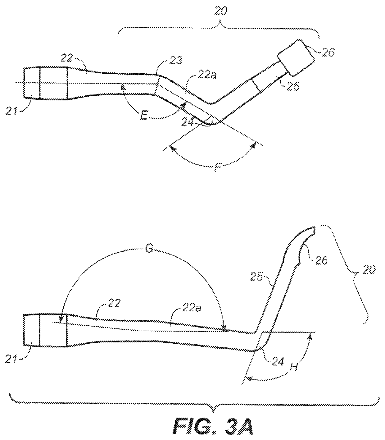
[0025]Referring to FIG. 1A, the elevator 1 is comprised of a base portion 2 that is comprised of a handle 2 or has a mating fixture (not shown) for attachment to a separate, reusable handle feature preferably having an ergonomic grip. The elevator 1 has a first elongated shaft region 3 and a second elongated shaft region 4 wherein the first and second elongated shaft regions are oriented by angle A having a range between 0° and 45° and terminate in a distal curved atraumatic tip 5. The outer edge 6 of the atraumatic tip 5 is rounded and curved to atraumatically engage tissue during a tunneling procedure. The distal end of the elevator 1 is comprised of an arc region 9 that terminates in the atraumatic tip 5. As is apparent from the side view of FIG. 1A, the atraumatic tip 5 is angled and curved relative to the second elongated shaft region 4 as indicated by the measurement of arc B. Arc B is preferably one-quarter circle but may range from a one-eighth circle to a one-half circle. T...


PUM


Abstract

The present invention is a group of surgical instruments with improved function and design for dental and craniofacial surgery, especially subperiosteal tunneling and related procedures. The instruments include surgical elevators for vestibular incision or incisions in the gingival sulcus. The instruments have varying angles and shapes to create a mucosal tunnel in any oral or maxillofacial region. The instrument suite also optionally includes specially designed forceps for introduction of graft material inside the subperiosteal tunnel and to assist with suturing of the graft to surrounding tissue.

Description

CROSS REFERENCE TO RELATED APPLICATIONS[0001]This application is related to and claims priority of U.S. provisional application (“Provisional Application”), Ser. No. 62 / 617,093, filed Jan. 12, 2018, entitled “Instruments and Methods for Subperiosteal Tunneling and Related Surgical Procedures.” The priority of this application is expressly claimed, and the disclosure is hereby incorporated by reference in their entirety.BACKGROUND OF THE INVENTION[0002]Mucosal surgery operations are common to treat dental and craniofacial disorders. Traditionally, mucosal surgical procedures require large incisions and reflection of a region of tissue called the mucoperiosteal flaps. These large flaps contain the vascular supply and are crucial to maintain the health of the mucosal tissue and surrounding structures. Large incisions and pronounced reflection of mucoperiosteal flaps cause delayed healing, excessive pain, inflammation, and the potential for edema. Traditional mucoperiosteal flap procedu...

Claims


Application Information

Patent Timeline
Patent Type & Authority Patents(United States)
IPC IPC(8): A61C8/00A61B90/00A61B17/04A61F2/28A61B17/30A61B17/32A61B17/29A61F2/46A61B17/00A61B17/02
CPCA61B90/08A61B17/0469A61B17/0482A61B17/30A61B17/32A61F2/2803A61B17/02A61B2017/0046A61B2017/00424A61B2017/00738A61B2017/2926A61B2017/301A61B2017/320056A61B2090/0817A61B2090/08021A61F2002/4622
Inventor ZADEH, HOMAYOUN H.
Owner ZADEH HOMAYOUN H
Learn More