Identification apparatus, identification system, and resin-selecting system
a technology of identification apparatus and identification system, which is applied in the direction of optical radiation measurement, instruments, spectrometry/spectrophotometry/monochromators, etc., can solve the problems of difficult identification stably, large variation in the intensity of raman-scattered light, etc., and achieve the effect of high degree of robustness
- Summary
- Abstract
- Description
- Claims
- Application Information
AI Technical Summary
Benefits of technology
Problems solved by technology
Method used
Image
Examples
first embodiment
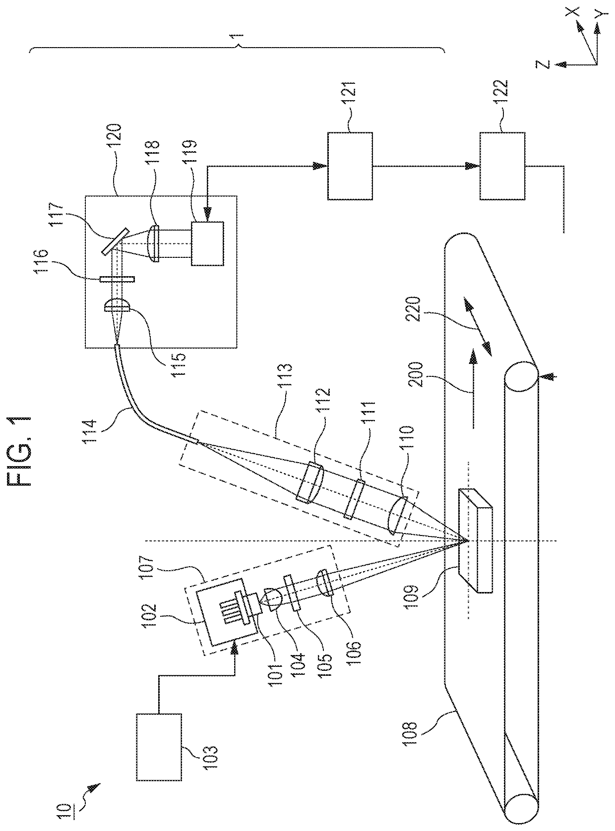
[0022]An identification apparatus according to a first embodiment of the present invention will be described with reference to FIG. 1. FIG. 1 schematically illustrates the structure of an identification system and the identification apparatus according to the first embodiment.
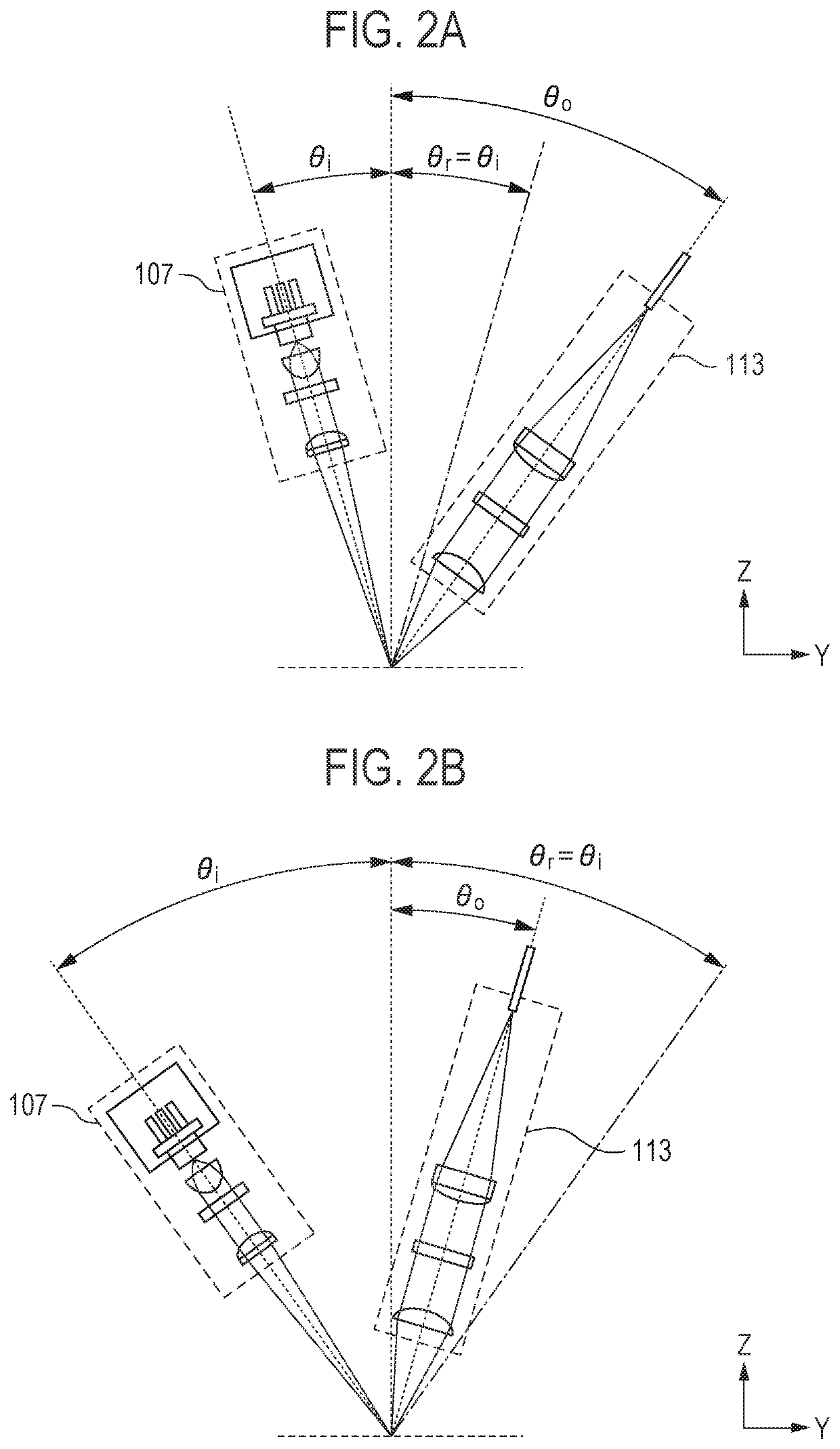
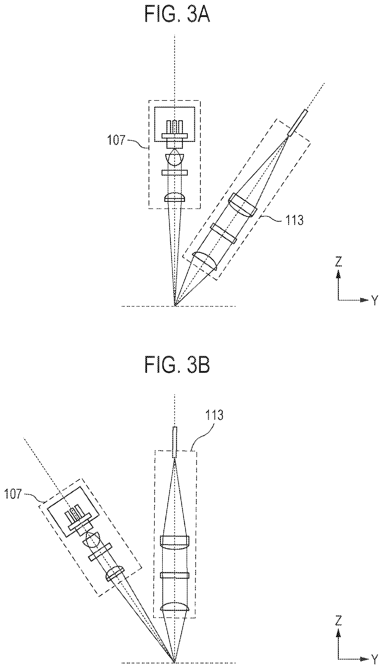
[0023]An identification apparatus 1 according to the present embodiment faces a conveyance surface of a conveyor 108 and identifies the kind of an object 109 that is conveyed by the conveyor 108. As illustrated in FIG. 1, the identification apparatus 1 includes an illumination optical system 107, a light capturing optical system 113, a spectral element 117, a light-receiving element 119, and a data-processing unit 121. An identification system 10 according to a modification to the present embodiment includes the conveyor 108, a conveyor-driving device 122, and the identification apparatus 1 that faces the conveyor 108. In FIG. 1, lines and directional straight lines that connect components represent optical pat...
second embodiment
[0056]An identification apparatus according to a second embodiment of the present invention will be described with reference to FIG. 4. Components common to those according to the first embodiment are designated by like reference characters, and a description thereof is omitted in some cases. FIG. 4 schematically illustrates the structure of an identification system and the identification apparatus according to the second embodiment.
[0057]An identification apparatus 2 according to the present embodiment includes capturing units 201 each of which includes the illumination optical system 107 and the light capturing optical system 113, and an optical fiber bundle 202 that includes the optical fibers 114 that guide the Raman-scattered light that is captured by the capturing units 201, and the optical fibers 114 are bundled near an exit end of the optical fiber bundle 202. The capturing units 201 face the conveyance surface of the conveyor 108 and are arranged at different positions in t...
third embodiment
[0067]A resin-selecting system according to a third embodiment of the present invention will be described with reference to FIG. 5. Components common to those according to the first embodiment and the second embodiment are designated by like reference characters, and a description thereof is omitted in some cases. FIG. 5 schematically illustrates the structure of the resin-selecting system according to the third embodiment.
[0068]A resin-selecting system 3 according to the present embodiment includes the identification apparatus 1 according to the first embodiment or the identification apparatus 2 according to the second embodiment, the conveyor 108, and a selection unit that is disposed nearer than the identification apparatus 1 or 2 to the downstream side of the conveyor 108. The selection unit selects the objects 109, based on an identification result of the identification apparatus 1 or 2. In the following description, the resin-selecting system 3 includes the identification appa...
PUM
| Property | Measurement | Unit |
|---|---|---|
| wavelength | aaaaa | aaaaa |
| wavelength | aaaaa | aaaaa |
| wavelength | aaaaa | aaaaa |
Abstract
Description
Claims
Application Information
 - R&D
- Intellectual Property
- Life Sciences
- Materials
- Tech Scout
- Unparalleled Data Quality
- Higher Quality Content
- 60% Fewer Hallucinations
Browse by: Latest US Patents, China's latest patents, Technical Efficacy Thesaurus, Application Domain, Technology Topic, Popular Technical Reports.
© 2025 PatSnap. All rights reserved.Legal|Privacy policy|Modern Slavery Act Transparency Statement|Sitemap|About US| Contact US: help@patsnap.com


