Combustion chamber assembly unit

a combustion chamber and assembly unit technology, applied in the direction of machine/engine, capillary burner, vehicle heating/cooling device, etc., can solve the problems of reducing the efficiency of the vehicle heater and high nitrogen oxide emission, and achieve the effect of reducing nitrogen oxide emission and high heat outpu

Active Publication Date: 2021-07-27
EBERSPACHER CLIMATE CONTROL SYST GMBH
View PDF15 Cites 0 Cited by
  • Summary
  • Abstract
  • Description
  • Claims
  • Application Information

AI Technical Summary

Benefits of technology

[0004]An object of the present invention is to provide a combustion chamber assembly unit for a fuel-operated vehicle heater, which vehicle heater reaches a high heat output with reduced nitrogen oxide emission while having a compact configuration.
[0006]By introducing a liquid cooling medium, for example, water, into the combustion air sent to the combustion chamber, a lowering of the combustion temperature is achieved in the area of the combustion chamber or of a volume area, which adjoins it and is formed, for example, in a flame tube, based on the high evaporation enthalpy provided by the liquid cooling medium. The lowering of the combustion temperature leads to a reduced percentage of nitrogen oxides in the waste gas, but it would basically reduce the efficiency of the vehicle heater, because the waste gas caused to interact thermally with a medium to be heated in a heat exchanger unit has a correspondingly lower temperature. However, since the waste gas leaving the combustion chamber or a flame tube transports the cooling medium vapor in the combustion chamber assembly unit configured according to the present invention and such a hot vapor has a markedly higher heat transfer coefficient than dry flue gas, the waste gas transporting the cooling medium vapor can transfer substantially more heat to a medium to be heated in the heat exchanger unit, as a result of which the lowering of the combustion temperature, brought about by the introduction of the liquid cooling medium, is compensated.
[0013]At least one cooling medium release opening and preferably each cooling medium release opening may be provided on a side of the line section that axially faces the combustion chamber bottom. The cooling medium released from the cooling medium feed line is released now into the combustion air essentially against the flow direction of the combustion air flowing around this line, so that a distribution of the liquid cooling medium in the combustion air already takes place during this process. As an alternative or in addition, provisions may be made for at least one cooling medium release opening and preferably for each cooling medium release opening to be provided on a side of the line section that faces axially away from the combustion chamber bottom. The cooling medium released from cooling medium release openings oriented in this manner is efficiently carried by the combustion air flowing around the cooling medium feed line and is guided in the direction of the combustion chamber.
[0017]A further reduction of the nitrogen oxide emission can be achieved in an advantageous variant by a reduction catalytic converter device, for example, an SCR catalytic converter device, around which waste gas can flow, being provided in an exhaust gas flow volume, and by the cooling medium feed device being configured for feeding a reducing agent as a liquid cooling medium. Thus, not only the effect of a flame temperature lowered by the evaporation of the reducing agent, but also the selective catalytic reduction taking place in the SCR catalytic converter device with the use of this evaporated reducing agent, which is transported in the waste gas stream, are utilized to bring about a substantial reduction of the percentage of nitrogen oxides in the waste gas.
[0020]It is proposed for a compact design having a simple configuration that the reduction catalytic converter device be integrated into the oxidation catalytic converter device. This can be achieved, for example, by the catalytic material of the reduction catalytic converter device being applied to surface areas of a substrate of the oxidation catalytic converter device.

Problems solved by technology

To achieve this at a sufficiently high efficiency, such vehicle heaters are operated with very high combustion temperatures, which, even though guaranteeing the provision of a large amount of thermal energy, on the one hand, does lead to a high nitrogen oxide emission, on the other hand.
The lowering of the combustion temperature leads to a reduced percentage of nitrogen oxides in the waste gas, but it would basically reduce the efficiency of the vehicle heater, because the waste gas caused to interact thermally with a medium to be heated in a heat exchanger unit has a correspondingly lower temperature.

Method used


Image

  • Combustion chamber assembly unit
  • Combustion chamber assembly unit
  • Combustion chamber assembly unit

Examples


Embodiment Construction

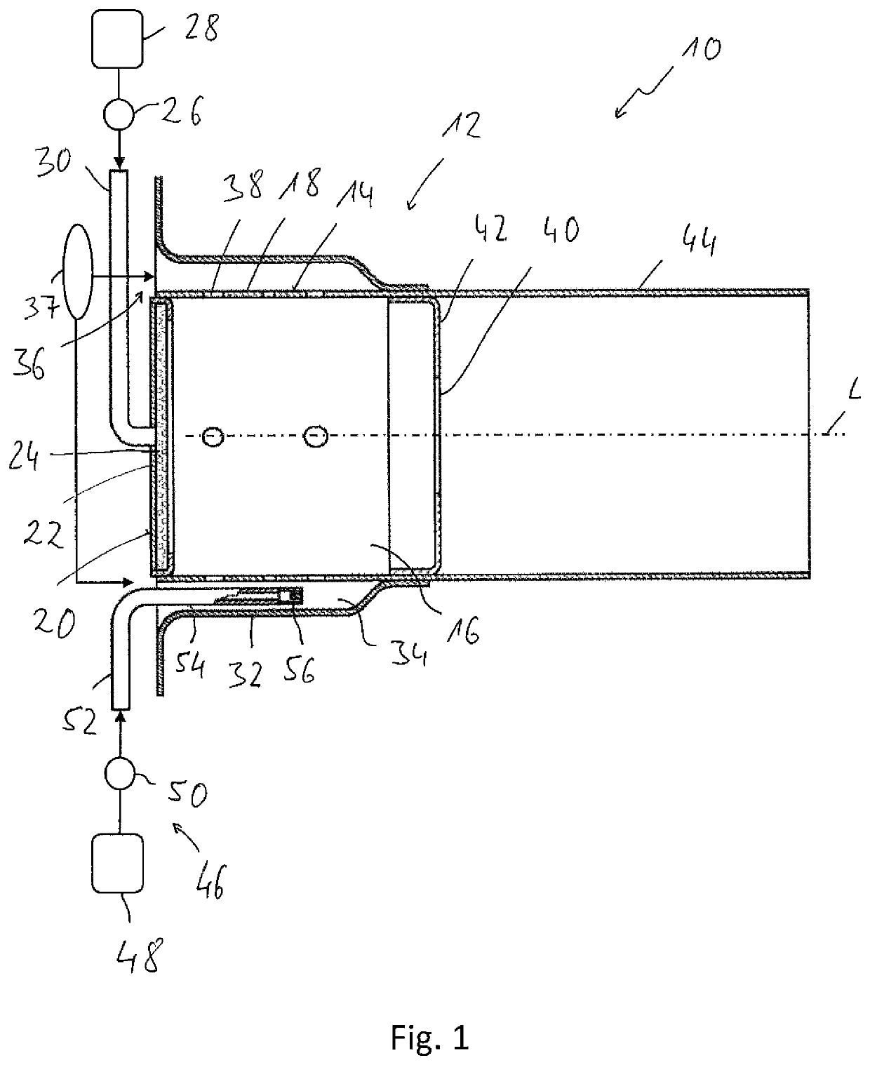
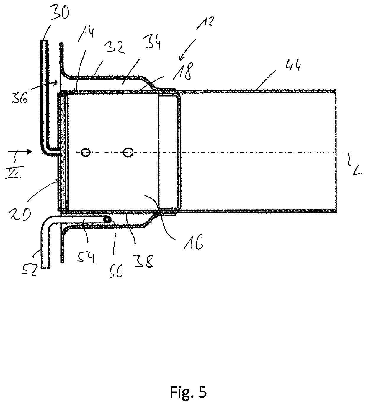
[0032]Referring to the drawings, A combustion chamber assembly unit for a fuel-operated vehicle heater 10 is generally designated by 12 in FIG. 1. The combustion chamber assembly unit 12 comprises a combustion chamber housing 14, which is elongated in the direction of a housing longitudinal axis L and has a combustion chamber circumferential wall 18 defining a combustion chamber 16 radially outwards. A combustion chamber bottom 20 is fixed at the combustion chamber circumferential wall 18. This bottom 20 defines the combustion chamber 16 axially and comprises a porous evaporator medium 24, e.g., a metal mesh, foam ceramic or the like, at a carrier device 22.

[0033]A fuel pump 26, for example, a feed pump, delivers liquid fuel from a fuel reservoir 28 via a fuel feed line 30 into the porous evaporator medium 24. The fuel fed in the liquid state is distributed in the porous evaporator medium 24 by capillary delivery action and is released as fuel vapor at a surface facing the combustio...


PUM

PropertyMeasurementUnit
volumeaaaaaaaaaa
combustion temperaturesaaaaaaaaaa
combustion temperatureaaaaaaaaaa

Abstract

A combustion chamber assembly unit for a fuel-operated vehicle heater includes a combustion chamber housing (14) elongated in a direction of a housing longitudinal axis (L), with a combustion chamber (16) radially outwardly bounded by a circumferential wall (18), and with a combustion chamber bottom (20) axially delimiting the combustion chamber (16). A combustion air feed volume (36) is provided that is open to the combustion chamber (16) via a plurality of passage openings (38). A cooling medium feed device (46) is provided for feeding a liquid cooling medium to the combustion air feed volume (36).

Description

CROSS REFERENCE TO RELATED APPLICATIONS[0001]This application claims the benefit of priority under 35 U.S.C. § 119 of German Applications 10 2018 119 701.2, filed Aug. 14, 2018 and 10 2018 127 168.9, filed Oct. 31, 2018, the entire contents of which are incorporated herein by reference.TECHNICAL FIELD[0002]The present invention pertains to a combustion chamber assembly unit for a fuel-operated vehicle heater.TECHNICAL BACKGROUND[0003]Such vehicle heaters, which are operated with fuel, for example, with diesel fuel or gasoline, i.e., especially liquid fuel, for example, as parking heaters or as auxiliary heaters, are used to heat the air to be introduced into the interior of a vehicle or to the liquid coolant circulating in a coolant circuit of an internal combustion engine. Since only little space is available, in general, for the installation of such vehicle heaters, these must have a compact configuration, but they nevertheless must be able to make available the necessary heat out...

Claims


Application Information

Patent Timeline
Patent Type & Authority Patents(United States)
IPC IPC(8): B60H1/00B60H1/04F02F1/10F02F1/24
CPCB60H1/04F02F1/10F02F1/24F23D3/40F23J15/02B60H1/2203F01P11/20F23J2215/40B60H2001/2271F23D14/78F23D2900/21002F23J2219/10B60H1/2212B01D53/9418B01D2251/2067B01D2258/012B60H2001/2281F23C99/008F23C2203/30F23D2900/05002F23J15/003F23J15/06F23J2215/10F23L7/002F23L2900/00001F23L2900/07008F23N2241/14Y02A50/20Y02E20/30Y02T10/12
Inventor HUMBURG, MICHAELPFISTER, WOLFGANGBLASCHKE, WALTER
Owner EBERSPACHER CLIMATE CONTROL SYST GMBH
Why Eureka
Try Eureka