Superconducting electromagnet apparatus and charged particle irradiation apparatus
a superconducting electromagnet and charge technology, applied in the direction of superconducting magnets/coils, magnetic bodies, therapy, etc., can solve the problems of local temperature rise, limit in reducing voltage, limit in increasing current, etc., and achieve the effect of reducing the stored energy of a superconducting electromagn
- Summary
- Abstract
- Description
- Claims
- Application Information
AI Technical Summary
Benefits of technology
Problems solved by technology
Method used
Image
Examples
first embodiment
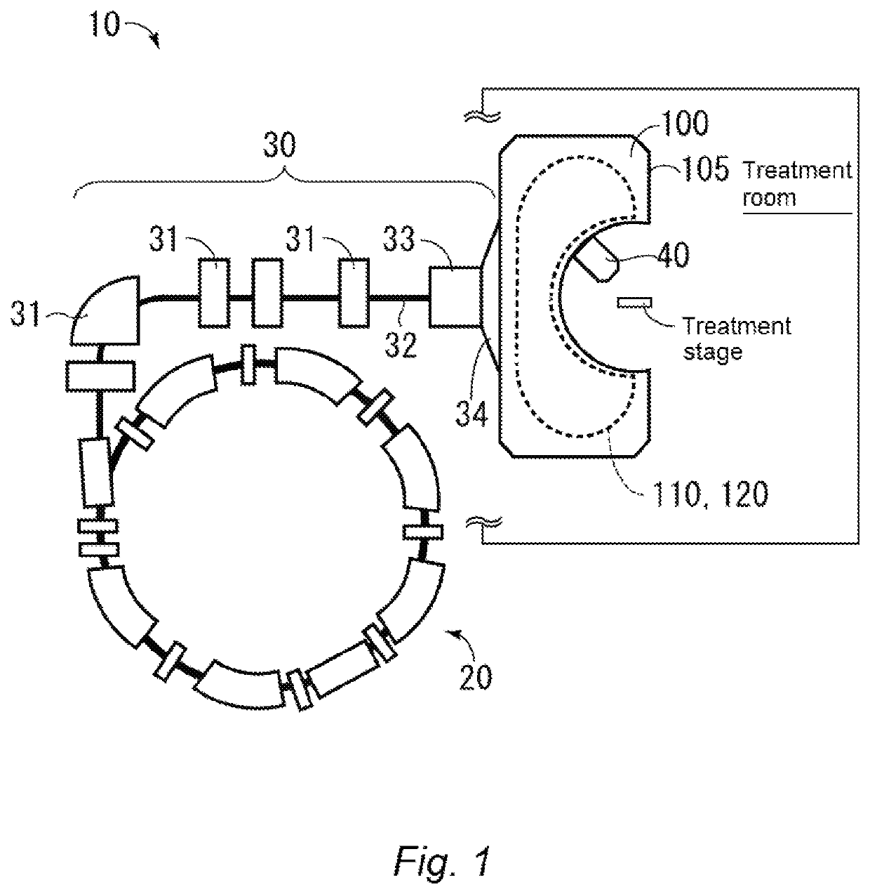
[0051]FIG. 1 is a schematic diagram of a configuration of a charged particle irradiation apparatus 10 having a superconducting electromagnet apparatus 100 according to a first embodiment of the present invention. The charged particle irradiation apparatus 10 has the superconducting electromagnet apparatus 100. The charged particle irradiation apparatus 10 may further have an accelerator 20, a charged particle beam transport system 30, and an irradiation nozzle 40. The irradiation nozzle 40 is arranged inside a treatment room provided with a treatment stage on which a patient is placed.
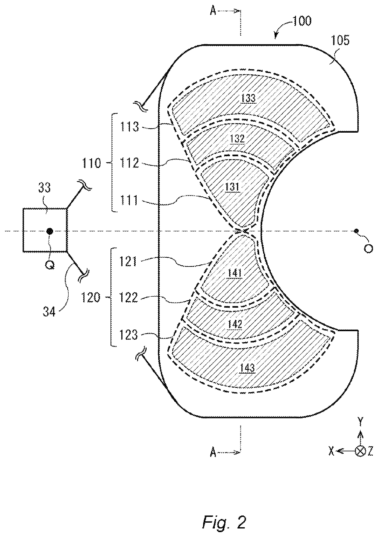
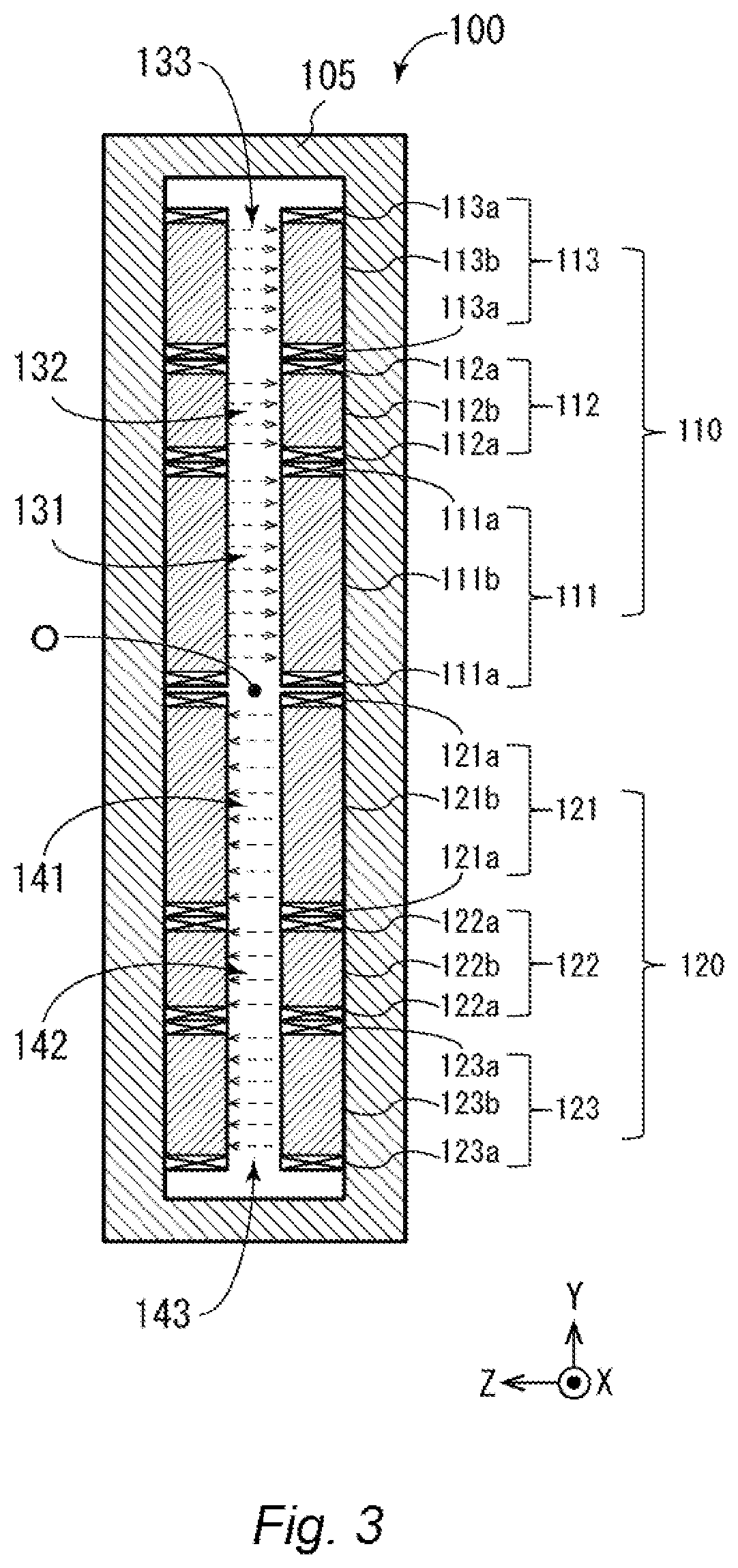
[0052]Groups of superconducting electromagnets 110 and 120 of the superconducting electromagnet apparatus 100 are included in a cryostat 105. The inside of the cryostat 105 is maintained at a cryogenic temperature. It may be preferable to maintain the effective magnetic field region in a vacuum as much as possible while maintaining the superconducting state of the superconducting electromagnet apparatu...
second embodiment
[0100]The second embodiment of the present invention relates to a configuration in which each of the superconducting electromagnets 111 to 113 of the group of superconducting electromagnets 110 is arranged inclined with respect to an adjacent superconducting coil on the XY plane. Note that the inclination in the Z-axis direction is not taken into consideration. Further, since the same applies to the group of superconducting electromagnets 120, the description thereof will be omitted.
[0101]As illustrated in FIG. 5A, on the XY plane, the superconducting electromagnet 112 forming the effective magnetic field region 132 is arranged inclined at an angle ψ with respect to the X-axis in accordance with the shape of the effective magnetic field region 131 of the adjacent superconducting electromagnet 111. That is, the effective magnetic field region 132 is inclined at the angle ψ with respect to the effective magnetic field region 131 and arranged adjacent to the effective magnetic field re...
third embodiment
[0105]The third embodiment of the present invention relates to a form in which the number of superconducting electromagnets 111 to 115 included in the group of superconducting electromagnets 110 included in the cryostat 105 is five and respective inductances L of the superconducting electromagnets 111 to 115 are the same (FIG. 6). Note that the same applies to the group of superconducting electromagnets 120, and the description thereof will be omitted. Further, the number of superconducting electromagnets is not limited to five in the present embodiment. Further, although the areas of the effective magnetic field regions 131 to 135 may seem to be unequal in a strict sense in FIG. 6, such inequality is not intended.
[0106]In the present embodiment, the plurality of superconducting electromagnets 111 to 115 have the effective magnetic field regions 131 to 135 having the area equal to each other on the XY plane, respectively. Further, respective magnetic flux densities B of the effectiv...
PUM
| Property | Measurement | Unit |
|---|---|---|
| deflection angle | aaaaa | aaaaa |
| deflection angle | aaaaa | aaaaa |
| deflection angle | aaaaa | aaaaa |
Abstract
Description
Claims
Application Information
 - R&D
- Intellectual Property
- Life Sciences
- Materials
- Tech Scout
- Unparalleled Data Quality
- Higher Quality Content
- 60% Fewer Hallucinations
Browse by: Latest US Patents, China's latest patents, Technical Efficacy Thesaurus, Application Domain, Technology Topic, Popular Technical Reports.
© 2025 PatSnap. All rights reserved.Legal|Privacy policy|Modern Slavery Act Transparency Statement|Sitemap|About US| Contact US: help@patsnap.com


