
Thin film transistor array substrate, display panel and display device

a thin film transistor and array substrate technology, applied in the field of display, can solve the problems of failure of the device, accumulation of stress between, formation of steps, etc., and achieve the effects of preventing the breakage of the film layer, reducing the internal stress of the electrostatic discharge device, and ensuring the elastic deformation spa

Active Publication Date: 2021-07-06
WUHAN CHINA STAR OPTOELECTRONICS TECH CO LTD
View PDF10 Cites 0 Cited by
  • Summary
  • Abstract
  • Description
  • Claims
  • Application Information

AI Technical Summary

Benefits of technology

The present invention reduces the internal stress of an electrostatic discharge device by dividing it into multiple units. This also provides space for elastic deformation during cutting, which prevents damage to the display panel and improves the cutting yield.

Problems solved by technology

During the production, the rubbing contact between an array substrate and a process machine is very likely to cause accumulation of static electricity, which results in electrostatic discharge (ESD) damage to an LTPS-TFT film layer and finally results in the failure of the devices.
However, in the related art, the film layer of the electrostatic discharge device has relatively large thickness and has a different coefficient of thermal expansion from other layers, so stress is accumulated between the film layer of the electrostatic discharge device and the other layers.
Meanwhile, there are relatively large differences between the film layer structure of the electrostatic discharge device and other regions, which results in the formation of steps.
When the array substrate and a color filter (CF) substrate are cut after being assembled, the heavily-doped poly-Si electrostatic discharge devices bear relatively large stress due to the existence of the steps, which causes the breakage of the film layer.

Method used


Image

  • Thin film transistor array substrate, display panel and display device
  • Thin film transistor array substrate, display panel and display device
  • Thin film transistor array substrate, display panel and display device

Examples


Embodiment Construction

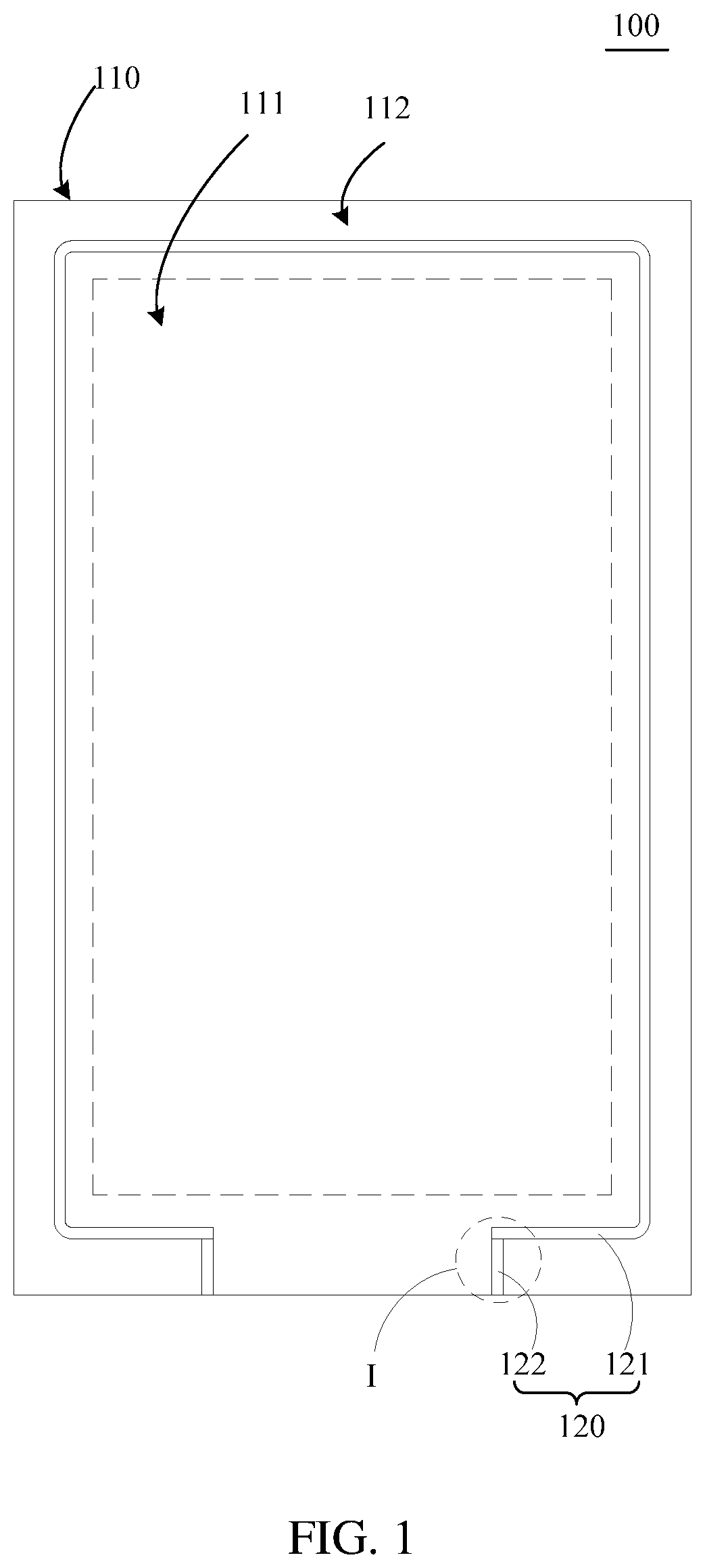
[0021]To make technical problems to be solved by the present disclosure, technical solutions adopted by the present disclosure and technical effects achieved by the present disclosure clearer, the technical solutions of embodiments of the present disclosure will be further described in detail hereinafter with reference to attached drawings.

[0022]In the description of the present disclosure, “a plurality of” means at least two, for example, two, three, etc., unless expressly limited. All directional instructions (such as upper, lower, left, right, front, back . . . ) in the present disclosure are only used to explain the relative position relationship and motion between components in a particular attitude (as shown in the attached drawings), and when the particular attitude changes, the directional instructions will also be changed accordingly. In addition, the terms “include”, “have” and any variation thereof are intended to encompass the items listed thereafter and equivalents ther...


PUM

PropertyMeasurementUnit
areaaaaaaaaaaa
conductiveaaaaaaaaaa
shapeaaaaaaaaaa

Abstract

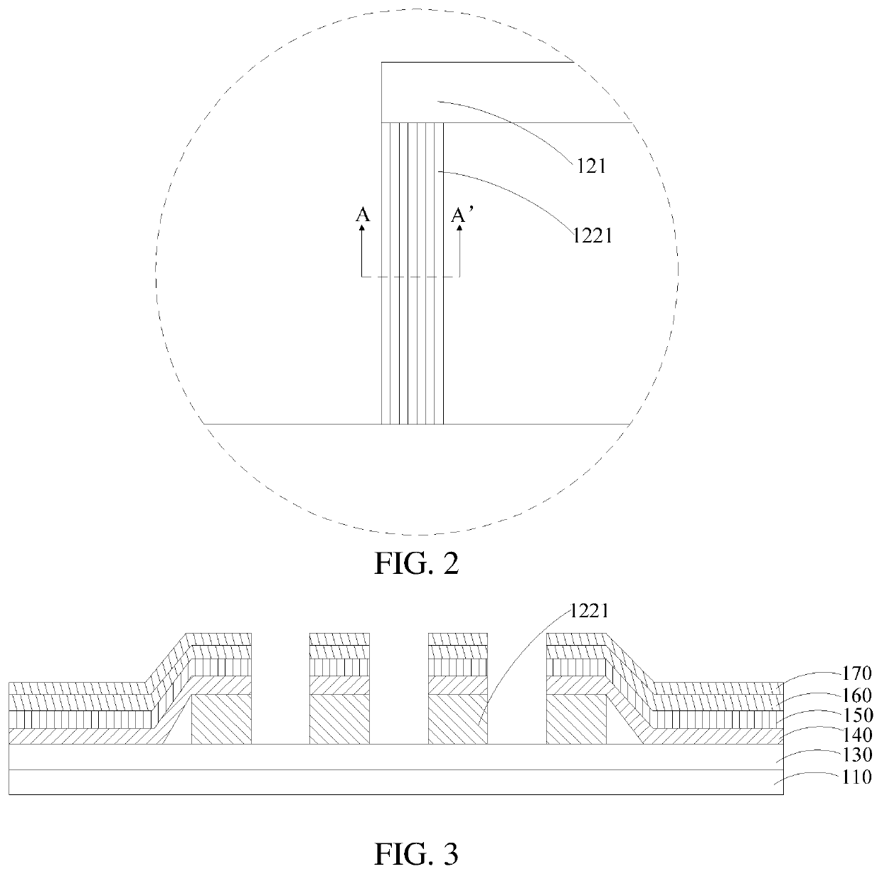
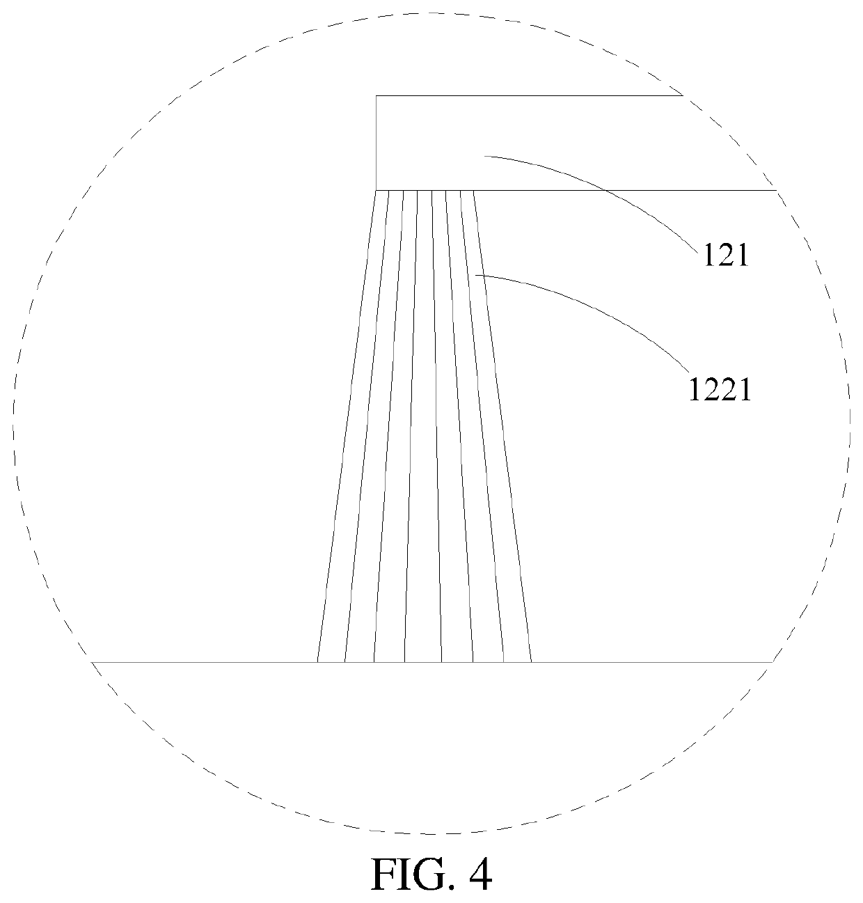
The present disclosure discloses a thin film transistor array substrate, a display panel and a display device. The array substrate includes a substrate and an electrostatic discharge circuit layer, and the electrostatic discharge circuit layer is disposed in the non-display area at a side of the substrate and includes a conductive circuit disposed around the display area and electrostatic discharge devices electrically connected with the conductive circuit. The electrostatic discharge device includes a plurality of electrostatic discharge units disposed at intervals, one end of each of the electrostatic discharge units is connected with an edge of the substrate and the other end thereof is connected with the conductive circuit.

Description

CROSS-REFERENCE TO RELATED APPLICATIONS[0001]The present application is a continuation-application of International (PCT) Patent Application No. PCT / CN2018 / 101643 filed on Aug. 22, 2018, which claims foreign priority of Chinese Patent Application No. 2018 / 10539241.1, filed on May 30, 2018 in the State Intellectual Property Office of China, the contents of all of which are hereby incorporated by reference.FIELD OF THE INVENTION[0002]The present disclosure generally relates to the technical field of displaying, and more particularly, relates to a thin film transistor (TFT) array substrate, a display panel and a display device.BACKGROUND OF THE INVENTION[0003]Low temperature poly-Si thin film transistors (LTPS-TFTs) are predominantly characterized by a high mobility of carriers and a small size of devices or the like, and thus become the key technology for developing display panels of low power consumption and a high integration degree. The manufacturing of LTPS-TFT array substrates re...

Claims


Application Information

Patent Timeline
Patent Type & Authority Patents(United States)
IPC IPC(8): H01L27/12H01L27/02G02F1/1362
CPCH01L27/1244H01L27/0266H01L27/1218G02F1/136204H01L27/0288H01L27/1214
Inventor NIE, XIAOHUIZHANG, JIAWEI
Owner WUHAN CHINA STAR OPTOELECTRONICS TECH CO LTD
Learn More