Micro-roughened electrodeposited copper foil and copper foil substrate

a technology of applied in the field of copper foil, can solve the problems of reducing the peel strength between copper foil and substrate, and achieve the effects of reducing the transmission loss of signals, good bonding strength, and good insertion loss performan

Active Publication Date: 2021-06-29
CO TECH DEV CORP
View PDF10 Cites 0 Cited by
  • Summary
  • Abstract
  • Description
  • Claims
  • Application Information

AI Technical Summary

Benefits of technology

[0016]One of the advantages of the present disclosure is that the micro-rough surface has good bonding strength relative to the substrate, and the copper foil substrate has good insertion loss performance and can significantly reduce the transmission loss of signals.

Problems solved by technology

However, the decrease of the surface roughness may reduce the peel strength between the copper foil and the substrate.
Therefore, how the peel strength can be maintained at the industry level and provide good insertion loss performance has become a problem to be solved in the related industry.

Method used


Image

  • Micro-roughened electrodeposited copper foil and copper foil substrate
  • Micro-roughened electrodeposited copper foil and copper foil substrate
  • Micro-roughened electrodeposited copper foil and copper foil substrate

Examples


example 1

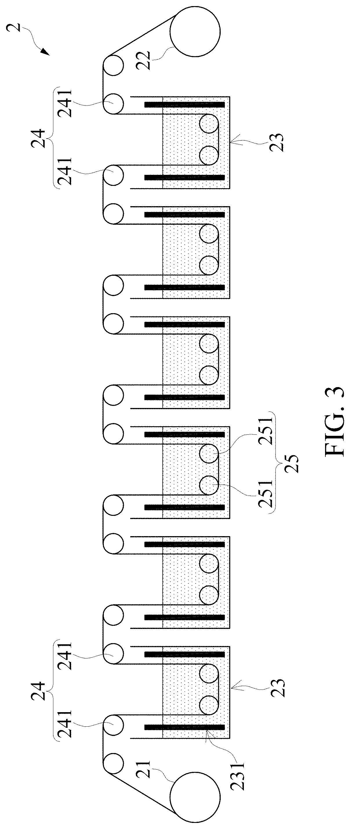
[0048]Referring to FIG. 3, a continuous-type electrolyzing apparatus 2, which can be used to perform electrolytic roughening treatment(s), is shown. The continuous-type electrolyzing apparatus 2 includes a feeding roll 21, a receiving roll 22, six tanks 23 (i.e., first to sixth tanks) arranged between the feeding roll 21 and the receiving roll 22, six electrolyzing roll assemblies 24 respectively arranged above the tanks 23, and six auxiliary roll assemblies 25 respectively arranged in the tanks 23. Each of the tanks 23 has a pair of platinum electrodes 231 arranged therein. Each of the electrolyzing roll assemblies 24 includes two electrolyzing rolls 241. Each of the auxiliary roll assemblies 25 includes two auxiliary rolls 251. The pair of platinum electrodes 231 in each of the tanks 23 and the corresponding electrolyzing roll assembly 24 are electrically connected to an anode and a cathode of an outer power supply, respectively.

[0049]In this example, a reverse treated copper foil...

examples 2 and 3

[0054]The raw foil, the electrolyzing apparatus and the composition of the copper-containing plating solution are the same as in Example 1. The electroplating conditions are shown in Table 1 and the production speed is 10 m / min. Two of the micro-roughened electrolysis copper foils of Example 2 and 3 are attached to an IT170GRA1 substrate. The copper foil substrates obtained are measured in the same ways as in Example 1, and the results are shown in Table 2.


PUM

PropertyMeasurementUnit
diameteraaaaaaaaaa
widthaaaaaaaaaa
widthaaaaaaaaaa

Abstract

A micro-roughened electrodeposited copper foil and a copper foil substrate are provided. The micro-roughened electrodeposited copper foil includes a micro-rough surface. The micro-rough surface has a plurality of peaks, a plurality of grooves and a plurality of micro-crystal clusters. Each of the grooves has a U-shaped or V-shaped cross-section profile, and the grooves have an average maximum width between 0.1 μm and 4 μm and an average depth less than or equal to 1.5 μm. Each of the micro-crystal clusters is composed of a plurality of micro-crystals each having an average diameter less than or equal to 0.5 μm grouped together. The micro-rough surface of the micro-roughened electrodeposited copper foil has an Rlr value less than 1.3. The micro-rough surface has good bonding strength relative to a substrate, and the copper foil substrate has good insertion loss performance to significantly reduce signal loss.

Description

CROSS-REFERENCE TO RELATED PATENT APPLICATION[0001]This application claims the benefit of priority to Taiwan Patent Application No. 107133827, filed on Sep. 26, 2018. The entire content of the above identified application is incorporated herein by reference.[0002]Some references, which may include patents, patent applications and various publications, may be cited and discussed in the description of this disclosure. The citation and / or discussion of such references is provided merely to clarify the description of the present disclosure and is not an admission that any such reference is “prior art” to the disclosure described herein. All references cited and discussed in this specification are incorporated herein by reference in their entireties and to the same extent as if each reference was individually incorporated by reference.FIELD OF THE DISCLOSURE[0003]The present disclosure relates to a copper foil, and more particularly to an electrodeposited copper foil and a copper foil su...

Claims


Application Information

Patent Timeline
Patent Type & Authority Patents(United States)
IPC IPC(8): B21C37/00C25D5/16C25D3/38C25D1/04
CPCC25D5/16C25D1/04C25D3/38Y10T428/12431C25D7/0614C25D5/617C25D5/605
Inventor SUNG, YUN-HSINGKAO, CHUN-YUWU, ZONG-XIAN
Owner CO TECH DEV CORP
Why Eureka
Try Eureka