Eureka AIR delivers breakthrough ideas for toughest innovation challenges, trusted by R&D personnel around the world.

Neural feedback loop filters for enhanced dynamic range magnetoencephalography (MEG) systems and methods

a dynamic range magnetoencephalography and neural feedback technology, applied in the field of magnetic field measurement systems, can solve the problems of prohibitively expensive for users and too large to be worn by users

Active Publication Date: 2021-06-01
HI LLC
View PDF154 Cites 1 Cited by
  • Summary
  • Abstract
  • Description
  • Claims
  • Application Information

AI Technical Summary

Problems solved by technology

In this disclosure the OPM is primarily considered because the SQUID requires cryogenic cooling, which may make it prohibitively costly for users and too large to be wearable by a user.

Method used


Image

  • Neural feedback loop filters for enhanced dynamic range magnetoencephalography (MEG) systems and methods
  • Neural feedback loop filters for enhanced dynamic range magnetoencephalography (MEG) systems and methods
  • Neural feedback loop filters for enhanced dynamic range magnetoencephalography (MEG) systems and methods

Examples


Embodiment Construction

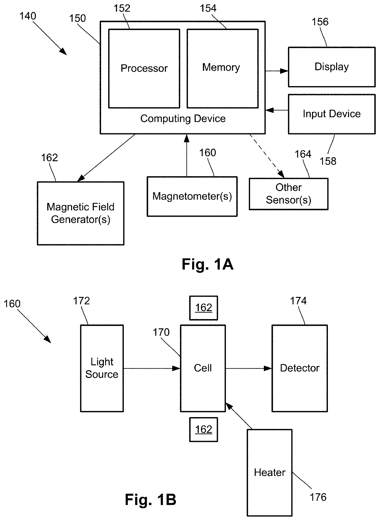
[0022]The present disclosure is directed to the area of magnetic field measurement systems using one or more optically pumped magnetometers. The present disclosure is also directed to magnetic field measurement systems and methods that include a feedback loop filter to facilitate detection or measurement of low amplitude magnetic fields.

[0023]Herein the terms “ambient background magnetic field” and “background magnetic field” are interchangeable and used to identify the magnetic field or fields associated with sources other than the magnetic field measurement system and the biological source(s) (for example, neural signals from a user's brain) or other source(s) of interest. The terms can include, for example, the Earth's magnetic field, as well as magnetic fields from magnets, electromagnets, electrical devices, and other signal or field generators in the environment, except for the magnetic field generator(s) that are part of the magnetic field measurement system.

[0024]The terms “...


PUM

PropertyMeasurementUnit
cutoff frequencyaaaaaaaaaa
magnetic fieldaaaaaaaaaa

Abstract

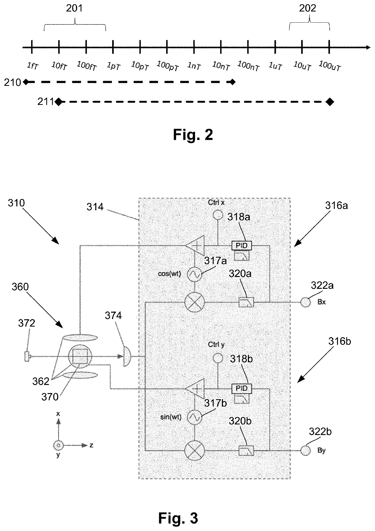
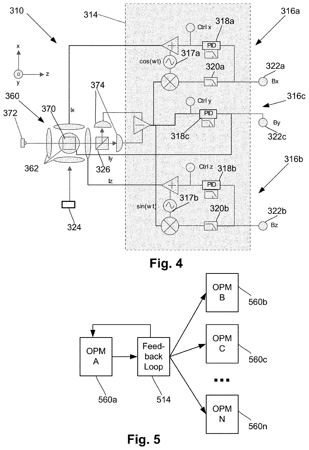
One embodiment is a magnetic field measurement system that includes at least one magnetometer having a vapor cell, a light source to direct light through the vapor cell, and a detector to receive light directed through the vapor cell; at least one magnetic field generator disposed adjacent the vapor cell; and a feedback circuit coupled to the at least one magnetic field generator and the detector of the at least one magnetometer. The feedback circuit includes at least one feedback loop that includes a first low pass filter with a first cutoff frequency. The feedback circuit is configured to compensate for magnetic field variations having a frequency lower than the first cutoff frequency. The first low pass filter rejects magnetic field variations having a frequency higher than the first cutoff frequency and provides the rejected magnetic field variations for measurement as an output of the feedback circuit.

Description

CROSS-REFERENCE TO RELATED APPLICATIONS[0001]This application claims the benefit of U.S. Provisional Patent Application Ser. No. 62 / 804,539, filed Feb. 12, 2019, and 62 / 837,574, filed Apr. 23, 2019, both of which are incorporated herein by reference in their entireties.FIELD[0002]The present disclosure is directed to the area of magnetic field measurement systems using one or more optically pumped magnetometers. The present disclosure is also directed to magnetic field measurement systems and methods that include a feedback loop filter to facilitate detection or measurement of low amplitude magnetic fields.BACKGROUND[0003]In the nervous system, neurons propagate signals via action potentials. These are brief electric currents which flow down the length of a neuron causing chemical transmitters to be released at a synapse. The time-varying electrical currents within an ensemble of neurons generates a magnetic field, which can be measured using either a Superconductive Quantum Interfe...

Claims


Application Information

Patent Timeline
Patent Type & Authority Patents(United States)
IPC IPC(8): G01R33/032G01R33/028G01R33/32G01N24/00G01R33/025G01R33/00
CPCG01R33/032G01N24/006G01R33/0041G01R33/025G01R33/028G01R33/326G01R33/26G01R33/0094A61B5/245
Inventor LEDBETTER, MICAHJIMÉNEZ-MARTINEZ, RICARDOPRATT, ETHANMOHSENI, HOOMANALFORD, JAMU
Owner HI LLC
Why Eureka
Eureka Blog
Learn More