
Artificial transmission line using t-coil sections

a technology of artificial transmission lines and coil sections, applied in the field of processing electrical signals, can solve problems such as difficult to efficiently implement structures (or none at all), and achieve the effect of difficult to efficiently implemen

Active Publication Date: 2021-05-11
ANALOG DEVICES INT UNLTD
View PDF49 Cites 1 Cited by
  • Summary
  • Abstract
  • Description
  • Claims
  • Application Information

AI Technical Summary

Benefits of technology

The present invention relates to a method for implementing transmission line structures in microwave and millimeter-wave circuits. The invention recognizes that constraints on the minimum length of transmission line structures may make it difficult to implement them in monolithic circuits or modules. To address this challenge, the invention proposes an artificial transmission line structure that can mimic the electrical properties of a corresponding actual transmission line structure. The artificial transmission line structure can be formed using lumped or discrete circuit elements and can include at least two unit cells. The invention also provides a technique for controlling a delay value for an electrical signal using a phase shifter circuit. The technical effects of the invention include efficient use of space and improved performance of transmission line structures in integrated circuits.

Problems solved by technology

The present inventors have recognized, among other things, that constraints on a minimum length of transmission line structures may make such structures difficult to implement efficiently (or at all) in radio frequency or microwave monolithic integrated circuits or integrated modules, particularly when an operating frequency is below about ten gigahertz (GHz), for example.

Method used


Image

  • Artificial transmission line using t-coil sections
  • Artificial transmission line using t-coil sections
  • Artificial transmission line using t-coil sections

Examples


Embodiment Construction

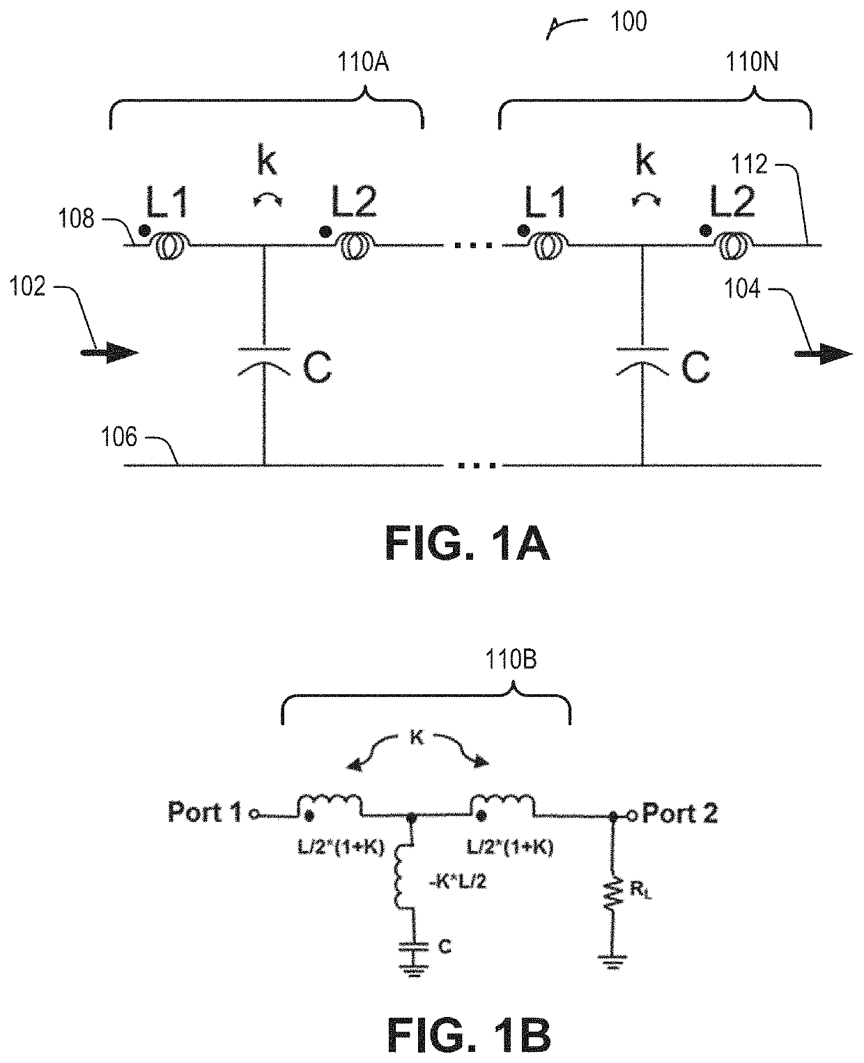
[0023]Transmission line structures generally have associated electrical characteristics such as a time delay (e.g., group delay), phase shift, characteristic impedance, or other parameters. As mentioned above, an artificial transmission line structure can be formed using lumped or discrete elements to provide electrical behavior similar to an actual transmission line structure. In an actual transmission line structure, electrical characteristics such as capacitance per unit length, inductance per unit length, conductance, and shunt resistance, generally result from distributed electrical characteristics of the conductors and dielectric materials forming the transmission line structure. By contrast, in an artificial transmission line structure, at least some electrical elements are lumped components, such as inductors or capacitors. Various topologies can be used to provide an artificial transmission line. For example, a left-handed artificial transmission line can be established usi...


PUM


Abstract

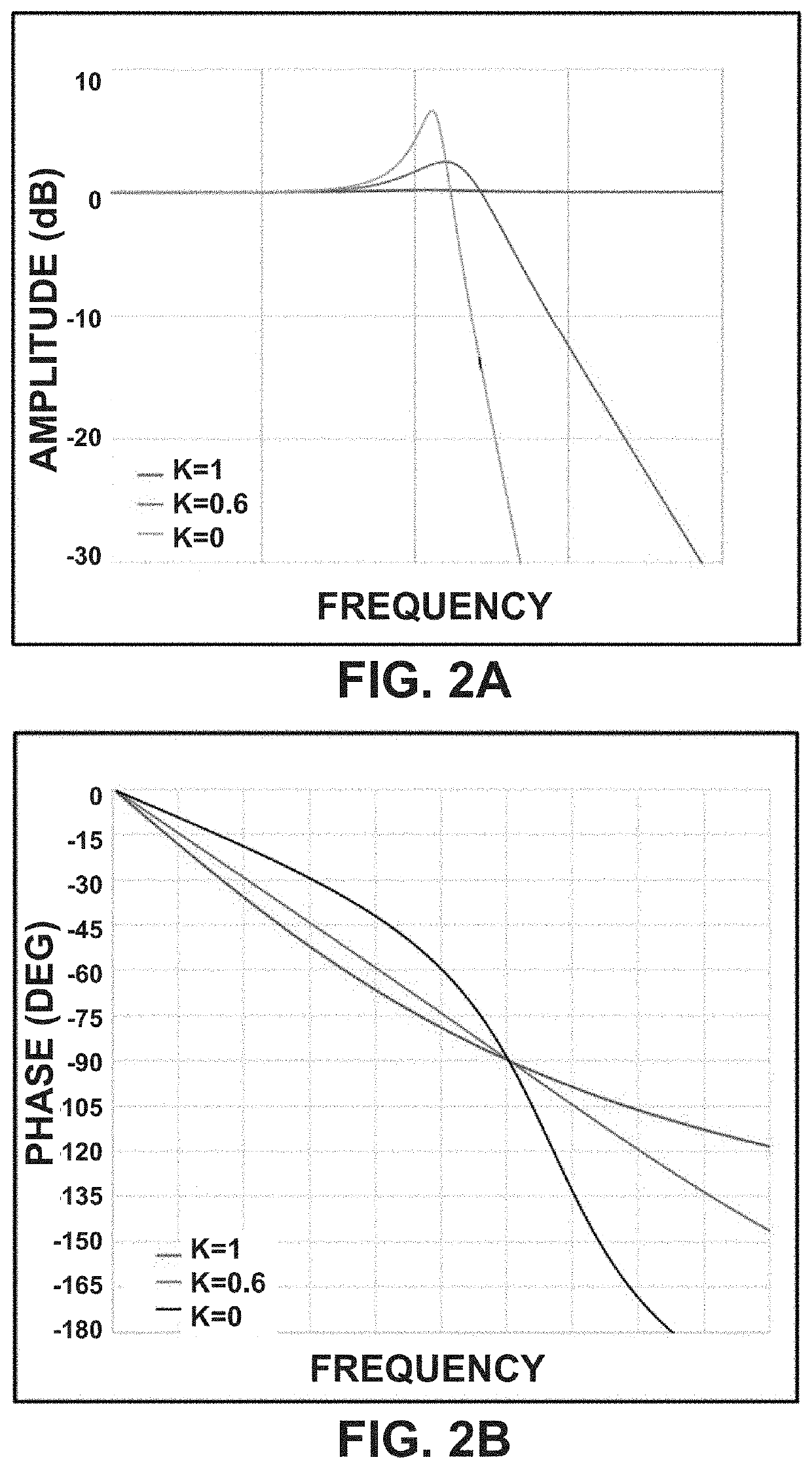
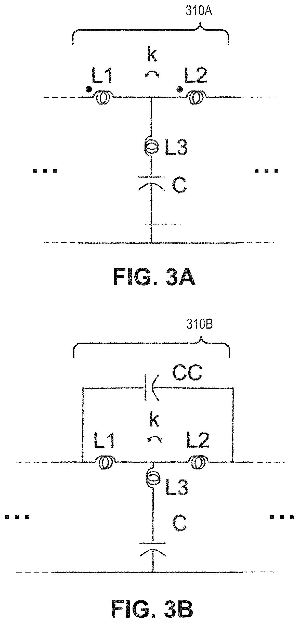
An electrical circuit can be formed at least in part using lumped or discrete circuit elements to provide an artificial transmission line structure that can mimic the electrical properties of a corresponding actual transmission line structure. Such an artificial transmission line structure can generally consume less area than an actual transmission line structure lacking such lumped or discrete elements. Such an artificial transmission line structure can be formed using two or more “unit cells” such as by cascading such cells as shown and described herein. The present inventors have recognized, among other things, that a unit cell of an artificial transmission line structure can include a t-coil section comprising magnetically-coupled inductors. Such an artificial transmission line structure can be used for applications such as phase shifting or to provide a delay line having a substantially constant group delay, among other applications.

Description

FIELD OF THE DISCLOSURE[0001]This document pertains generally, but not by way of limitation, to apparatus and techniques that can be used for processing electrical signals in the analog domain, and more particularly, to one or more of filtering or delaying electrical signals using transmission-line-like behavior.BACKGROUND[0002]A transmission line structure can be defined as an electrical structure where the physical dimensions of the structure are comparable to or greater than a wavelength of a signal being conveyed by the transmission line structure. For example, structures that have physical dimensions (such as length) that are comparable to at least a tenth of a wavelength, at least a quarter of a wavelength, at least a half of a wavelength, or greater in extent, can be referred to as exhibiting transmission line characteristics. In another formulation, a transmission line structure can be considered an electrical structure where the electrical characteristics of the transmissio...

Claims


Application Information

Patent Timeline
IPC IPC(8): H03H7/09H03H7/18
CPCH03H7/18H03H7/32H03H7/09H03H7/20
Inventor WANG, XUDONGBAGWELL, MICHAEL W.BECKWITH, WILLIAM B.SCHILTZ, THOMAS E.
Owner ANALOG DEVICES INT UNLTD
Learn More