Ultrasonic imaging device
a technology of ultrasonic imaging and imaging device, which is applied in the field of ultrasonic imaging technique, can solve the problems of difficult realization of azimuth direction resolution improvement and hard to improve azimuth direction resolution
- Summary
- Abstract
- Description
- Claims
- Application Information
AI Technical Summary
Benefits of technology
Problems solved by technology
Method used
Image
Examples
first embodiment
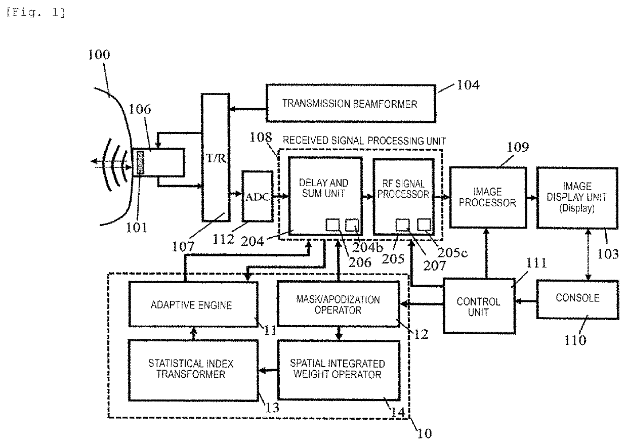
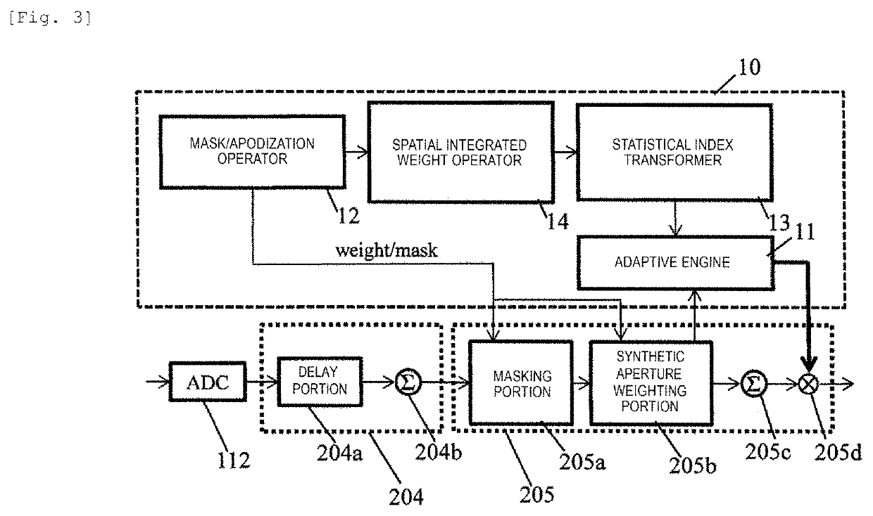
[0045]In a first embodiment, a description will be made of a configuration in which the weighting unit 10 weights an RF signal having undergone synthetic aperture imaging in the RF signal processor 205 with an adaptive weight (Ψ). In the present embodiment, the weighting unit 10 generates the adaptive weight (Ψ) by taking into consideration that the number of signals undergoing synthetic aperture imaging for each reception focal point dynamically forms different spatial distributions depending on a difference in a position of the reception focal point.
[0046]First, a description will be made of the configuration of the weighting unit 10 with reference to FIGS. 1 and 3. The weighting unit 10 includes an adaptive engine 11 which obtains an adaptive weight, a mask / apodization operator 12, a statistical index transformer 13, and a spatial integrated weight operator 14. The adaptive engine 11 adaptively calculates a weight by using coherence (phase coincidence, signal similarity, or corre...
second embodiment
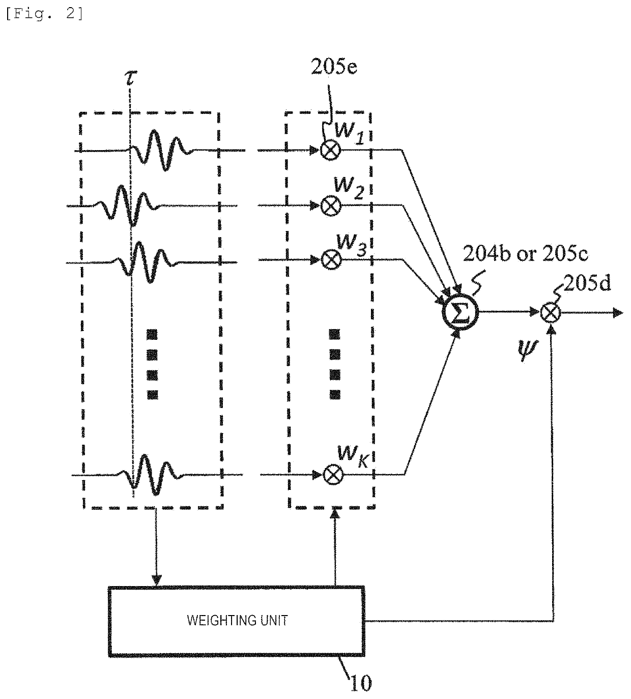
[0067]In the first embodiment, the RF signal processor 205 weights an RF signal having undergone synthetic aperture imaging with the adaptive weight (Ψ), but, in the second embodiment, the RF signal processor 205 weights RF signals not having undergone synthetic aperture imaging with adaptive weights (w1 to wk), respectively. In the present embodiment, the weighting unit 10 generates the adaptive weights (w1 to wk) by taking into consideration that the number of signals undergoing synthetic aperture imaging for each reception focal point is distributed depending on a reception focal point.
[0068]FIG. 8 illustrates a configuration of the weighting unit 10 of the second embodiment, and FIG. 9 illustrates a flow showing an operation thereof. As illustrated in FIG. 8, a configuration of the weighting unit 10 of the second embodiment is the same as the configuration in the first embodiment illustrated in FIG. 3 except that the adaptive engine 11 obtains the adaptive weights (w1 to wk) for...
third embodiment
[0085]In the third embodiment, a description will be made of a configuration in which the weighting unit 10 weights an RF signal obtained as a result of summing in the delay and sum unit 204 with the adaptive weight (Ψ). In the present embodiment, the weighting unit 10 generates the adaptive weight (Ψ) by taking into consideration that the number of delayed and summed signals is distributed depending on a position of a reception focal point.
[0086]As illustrated in FIG. 10, in the third embodiment, the same masking portion 204c and delay and sum weighting portion 204d as the masking portion 205a and the synthetic aperture weighting portion 205b of the first embodiment are disposed between the delay portion 204a and the summing portion 204b of the delay and sum unit 204. A multiplication portion 204e is disposed in the rear stage of the summing portion 204b.
[0087]The mask / apodization operator 12 generates, as a mask for the masking portion 204c and a weight for the delay and sum weig...
PUM
 Abstract
Description
Claims
Application Information
 - R&D
- Intellectual Property
- Life Sciences
- Materials
- Tech Scout
- Unparalleled Data Quality
- Higher Quality Content
- 60% Fewer Hallucinations
Browse by: Latest US Patents, China's latest patents, Technical Efficacy Thesaurus, Application Domain, Technology Topic, Popular Technical Reports.
© 2025 PatSnap. All rights reserved.Legal|Privacy policy|Modern Slavery Act Transparency Statement|Sitemap|About US| Contact US: help@patsnap.com


