
Method for determining characteristics of holes to be provided through a plate and corresponding programme

a technology of characteristics and holes, applied in the direction of cad circuit design, lighting and heating apparatus, instruments, etc., can solve the problems of poor distribution or share, hot points and/or short circuits, reducing the performance of heat exchangers, etc., and achieves fast and reliable results. , the effect of improving uniformity

Active Publication Date: 2018-08-14
CENT NAT DE LA RECHERCHE SCI +1
View PDF4 Cites 0 Cited by
  • Summary
  • Abstract
  • Description
  • Claims
  • Application Information

AI Technical Summary

Benefits of technology

The present invention provides a method for determining the optimal distribution of fluid passages in a plate used in fluid flow circuits. This method allows for better fluid distribution, resulting in improved efficiency and reduced risk of damage to the installation. The method makes use of the flow rate density parameter to obtain a more uniform distribution of fluid downstream from the plate. The ratio of the diameter and length of the fluid passage segment is also important in achieving improved uniformity of speed downstream from the plate. The invention provides a circuit design method that includes a plate designed using the optimal distribution method described above.

Problems solved by technology

In particular, in a heat exchanger that comprises two transfer circuits passing two distinct fluids, and arranged relative to each other so as to transfer heat from the fluid flowing in one of the transfer circuits to the fluid flowing in the other transfer circuit, a poor distribution or share of fluid in one and / or the other of said circuits has the consequence of reducing the performance of said heat exchanger, and possibly of leading to hot points and / or short circuits.
There is also a risk of said heat exchanger being damaged.
Nevertheless, the characteristics, of the orifices are selected empirically for each circuit shape, which does not make it possible to obtain uniformity of fluid stream distribution in reliable and repeatable manner from one circuit shape to another, or from one operating point to another.
Furthermore, numerous tests are needed and such a process presents a cost that is high, effectiveness that is poor, and takes a very long time.

Method used


Image

  • Method for determining characteristics of holes to be provided through a plate and corresponding programme
  • Method for determining characteristics of holes to be provided through a plate and corresponding programme
  • Method for determining characteristics of holes to be provided through a plate and corresponding programme

Examples


Embodiment Construction

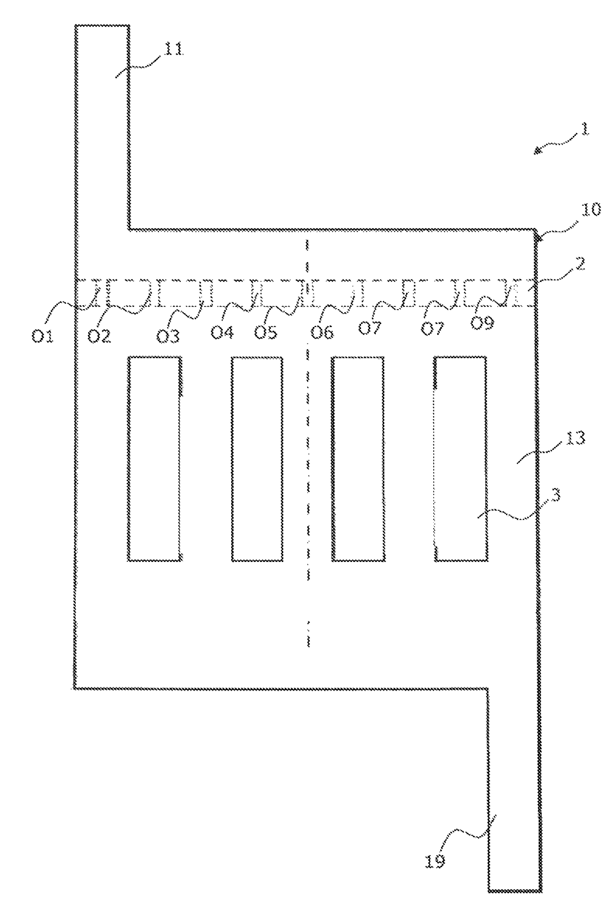
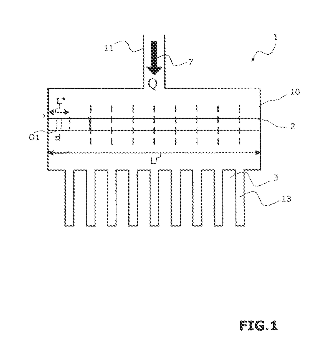
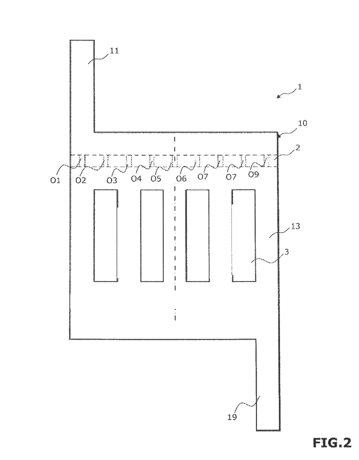
[0074]With reference to the figures and as summarized above, the invention relates to a method of determining the characteristics of orifices to be made through a plate 2 that is positioned in a circuit in order to make uniform the distribution and preferably also the speeds of the fluid downstream from said plate 2.

[0075]As described in detail below, the characteristics of the orifices comprise in particular the number, the diameters, and possibly the relative positions of each of the orifices. In the example shown in the figure, there are nine such orifices referenced O1 to O9. Naturally, the number of orifices could be different, and it is written N.

[0076]Said plate 2 is positioned in the circuit 10 across the fluid passage 7 downstream from the inlet 11 of the circuit.

[0077]In the example shown in the figures, the circuit 10 forms a portion of a heat exchanger 1 and has a portion 13 forming parallel fluid ducts arranged with ducts 3 of another fluid circuit of said heat exchange...


PUM

PropertyMeasurementUnit
pressureaaaaaaaaaa
heat fluxaaaaaaaaaa
gravityaaaaaaaaaa

Abstract

The invention relates to a method of determining characteristics of orifices (O1, . . . , O9) to be made through a plate (2) positioned in a circuit (10) across the fluid passage. Said method comprises defining fluid data, the number of orifices, and for each orifice a control segment or area. The fluid flow rate through each orifice of the perforated plate is calculated, and for each orifice, the flow rate density is calculated by dividing said fluid flow rate by the associated control segment length or control area. The optimized or non-optimized nature of the orifice characteristic is determined by comparing said flow rate density with the mean flow rate density. If the difference in absolute value lies within a predetermined range of values, then the orifice characteristics are considered as being optimized. Otherwise at least one characteristic of at least some of the orifices is modified.

Description

RELATED APPLICATIONS[0001]This application is a National Phase Application of PCT / FR2014 / 052145, filed on Aug. 29, 2014, which in turn claims the benefit of priority from French Patent Application No. 13 58304 filed on Aug. 30, 2013, the entirety of which are incorporated herein by reference.BACKGROUNDField of the Invention[0002]The present invention relates in general manner to distributing fluid in a circuit.Description of Related Art[0003]In order to operate well, equipment having a circuit that passes a fluid needs to have the fluid properly distributed in said circuit. In particular, in a heat exchanger that comprises two transfer circuits passing two distinct fluids, and arranged relative to each other so as to transfer heat from the fluid flowing in one of the transfer circuits to the fluid flowing in the other transfer circuit, a poor distribution or share of fluid in one and / or the other of said circuits has the consequence of reducing the performance of said heat exchanger...

Claims


Application Information

Patent Timeline
Patent Type & Authority Patents(United States)
IPC IPC(8): G06F17/50F28F9/02G01N15/08G01N30/60
CPCG06F17/5072F28F9/028G01N15/088G06F17/5018F28F9/0278G01N30/6017G06F2119/08G06F30/23G06F30/39G06F30/392
Inventor FLAMANT, GILLESLUO, LINGAIFAN, YILINWEI, MIN
Owner CENT NAT DE LA RECHERCHE SCI
Learn More