
Procedure and system for manufacturing a part made from composite material and part made from composite material obtained by means of said method

a technology of composite materials and manufacturing methods, applied in the direction of additive manufacturing, manufacturing tools, coatings, etc., can solve the problems of increasing the cost of the manufacturing method, slowing down the manufacturing method, and imposing serious limitations on the geometries of the parts obtained

Active Publication Date: 2021-04-06
FUNDACIO EURECAT
View PDF8 Cites 0 Cited by
  • Summary
  • Abstract
  • Description
  • Claims
  • Application Information

AI Technical Summary

Benefits of technology

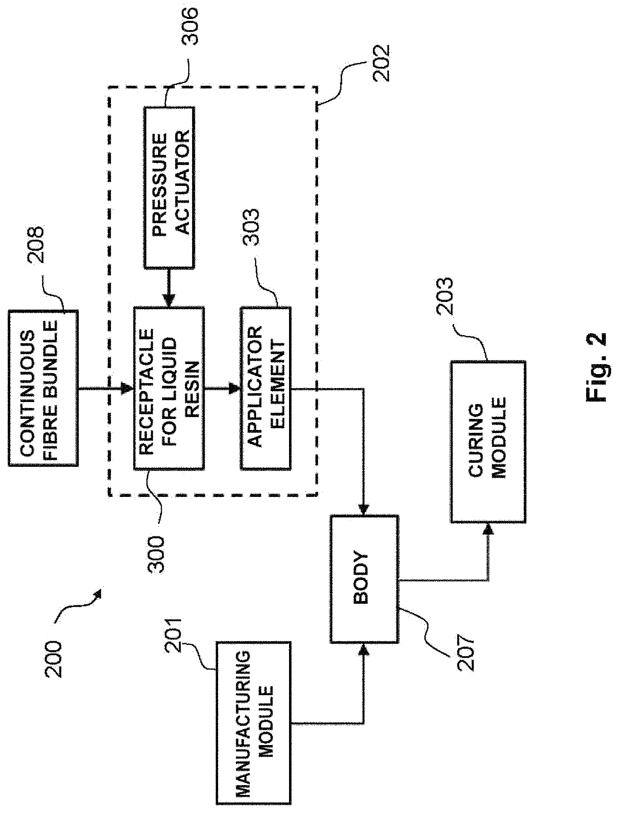
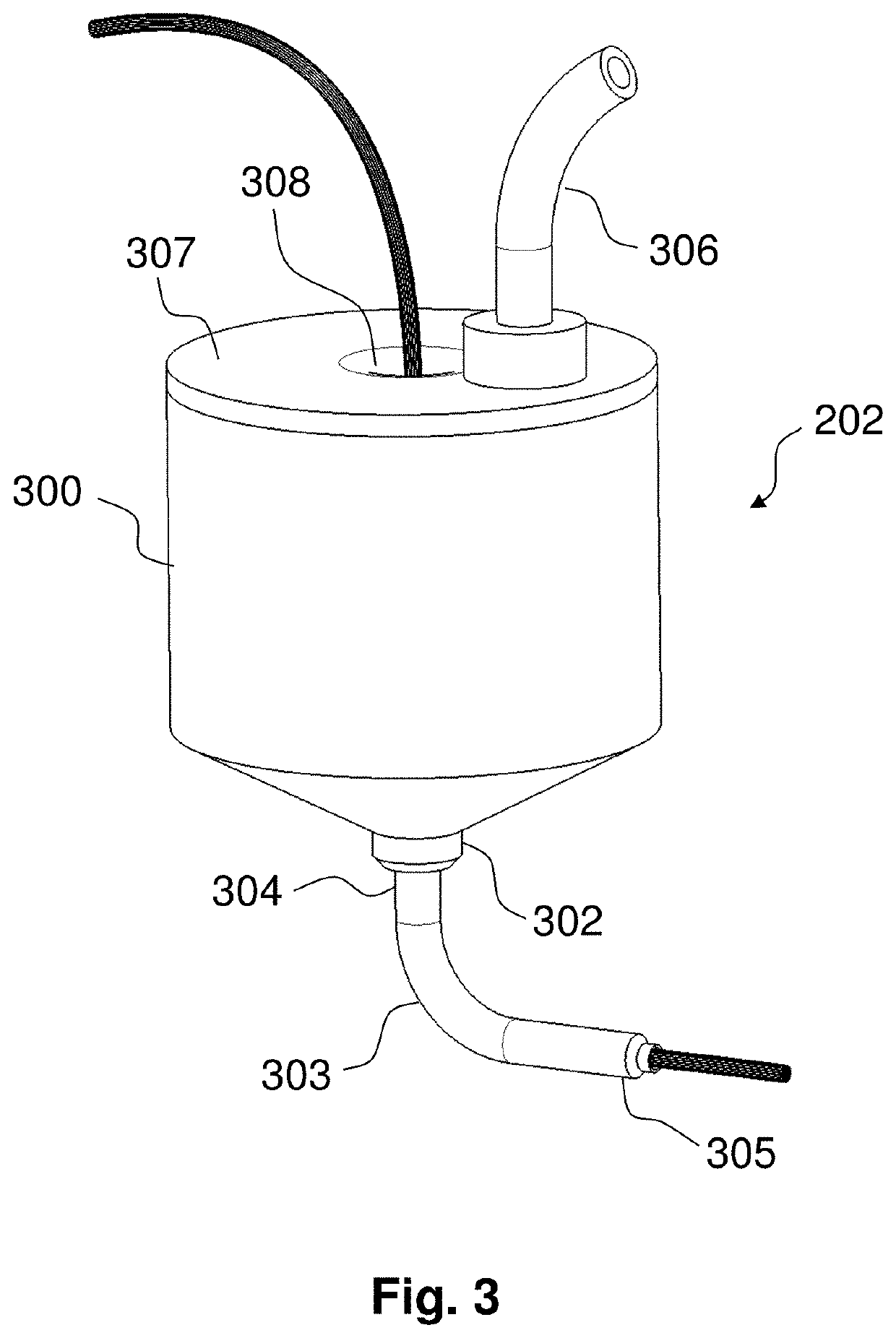
The patent is about a new way to make parts using a continuous fiber reinforcement process. This process can be done using traditional methods like layer stacking or pultrusion, or by using a new system that allows for more complex part geometries. The process includes using multiple applicator elements and a receptacle with multiple outlet openings, which allows for the insertion of different fiber bundles at the same time. This reduces the time needed to reinforce a part. Overall, this patent introduces a new way to make stronger parts faster and more efficiently.

Problems solved by technology

The manufacturing methods based on these technologies impose serious limitations on the geometries of the parts obtained, which are generally simple shapes such as plates and surfaces (flat or having a certain curvature), hollow tubular structures and extruded profiles having a constant cross-section.
This slows down the manufacturing method and raises its cost, in addition to generate a lot of waste composite material.
Another limitation of the manufacturing methods of parts made from composite material of the state of the art is that the continuous fibres are confined to the laminate plane, not being possible to orient them freely in the three dimensions of the part.
For this reason, the parts obtained by means of these manufacturing methods have low resistance to interlayer delamination.
Additionally, the known manufacturing methods are not appropriate for obtaining composite materials wherein continuous-fibre reinforcement must be combined with a non-polymer matrix, such as for example ceramic or metallic.
Due to being based on adding material rather than removing it as in most manufacturing processes, additive manufacturing technologies enable the manufacture of highly complex geometries, impossible to obtain by means of other technologies, and even mechanisms that comprise a set of pre-assembled parts, producing very little wastage of material.
(https: / / markforged.com / mark-one / ) enable the obtainment of continuous fibre-reinforced parts by means of additive manufacturing, but with the limitations that the reinforcement can only be disposed layer by layer and work only with thermoplastics.

Method used


Image

  • Procedure and system for manufacturing a part made from composite material and part made from composite material obtained by means of said method
  • Procedure and system for manufacturing a part made from composite material and part made from composite material obtained by means of said method
  • Procedure and system for manufacturing a part made from composite material and part made from composite material obtained by means of said method

Examples


example 1

[0146]FIGS. 6a-c show, respectively, a profile and front perspective view of an example of a part made from composite material manufactured using the method of the present invention. Specifically, the part 600 comprises a body 601 having four support zones 602a-d on its lower part and a load zone 603 on its upper part. The part 600 has been designed to support a force exerted on the load zone 603 and aimed vertically towards the plane whereon the four support zones 602a-d rest. In particular, the dimensions of the part 600 are 175 mm×80 mm×65 mm.

[0147]The shape of the body 601 has been calculated using topology optimisation tools based on the finite element method to automatically optimise the geometry of the body 601, removing material from those zones subject to less mechanical stress. Upon optimising the geometry of the body 601, the path of the continuous fibre bundles has been determined (and, correspondingly, of the tubular cavities that will house them) through the interior o...

example 2

[0163]FIG. 8 shows a second example of a part made from composite material whose body has been obtained by joining a plurality of elements. In particular, the body 800 of the part comprises a plurality of elements 801-810, each element having at least one tubular cavity segment in its interior. FIG. 8 shows a cross-section of the body 800 in order to be able to observe the tubular cavity segments disposed in elements 801-810.

[0164]As can be observed in the figure, not all the elements 801-810 have the same shape and / or dimensions. Therefore, while the elements 801-805 are substantially cylindrical and elongated, the elements 806-810 are substantially spherical or ellipsoidal and act as joining elements of the former. Also, each of the elements 806 and 809 contain two independent tubular cavity segments in their interior, while each of the elements 801-805, 807, 808 and 810 include only one in their interior.

[0165]In accordance with the method of the present invention, the elements 8...


PUM

PropertyMeasurementUnit
lengthsaaaaaaaaaa
lengthsaaaaaaaaaa
lengthsaaaaaaaaaa

Abstract

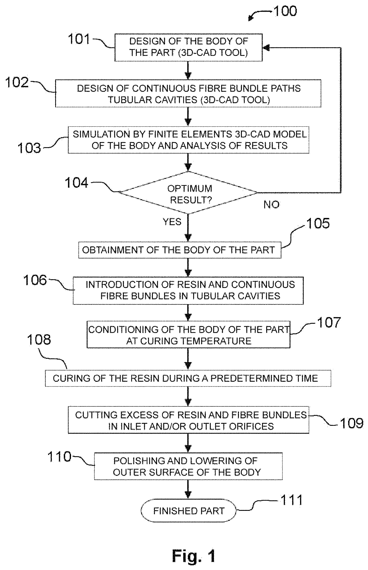
The invention relates to a method for manufacturing a part made from composite material, having a body and one or more continuous fibre bundles in its interior, characterised in that it comprises the stages of: a) obtaining a body that includes one or more tubular cavities in its interior that extend between a first end, disposed on the outer surface of the body and which comprises an inlet orifice, and a second end, opposite to the first end; b) introducing resin in the liquid state and a continuous fibre bundle in the interior of at least one tubular cavity through its inlet orifice; and c) curing the resin until it solidifies, adhering to the body and fixing the continuous fibre bundle. The invention also relates to a system for manufacturing a part made from composite material and to the part made from composite material obtained.

Description

[0001]The present relates to a method for manufacturing a part made from composite material with which it is possible to obtain parts with complex geometric shapes and with enhanced features. In addition, the method of the present invention makes it possible to easily combine different kinds of materials, enabling the production of parts from a wide variety of composite materials. The present invention also relates to a system for manufacturing a part made from composite material and to a part made from composite material obtained by means of said method.BACKGROUND OF THE INVENTION[0002]Composite materials, or composites, are widely used in multiple industries, such as the aerospace, automotive, energy or construction industry, inter alia. A composite material is a material formed from various materials which have been specially selected and configured to combine their properties, thereby obtaining a new material, composite, with enhanced mechanical, thermal and / or chemical features...

Claims


Application Information

Patent Timeline
Patent Type & Authority Patents(United States)
IPC IPC(8): B29C70/20B33Y10/00B29C64/118B29K105/08B29B15/12B29C70/74B29C70/48B33Y30/00B33Y80/00B29K63/00B29K67/00B29K309/08
CPCB29B15/122B29C64/118B29C70/20B29C70/205B29C70/48B29C70/745B33Y10/00B33Y30/00B33Y80/00B29B15/125B29K2063/00B29K2067/046B29K2105/08B29K2309/08
Inventor CRESCENTI SAVALL, MARCLLUIS RODRIGUEZ, JOSE MARIA
Owner FUNDACIO EURECAT
Learn More