
Piezoelectric element and device using same

a piezoelectric element and piezoelectric fiber technology, applied in the field of fiberlike piezoelectric elements, can solve the problems of insufficient electrical output that cannot be obtained by tension or compression, no technology for generating and extracting sufficient electrical output, and extremely difficult to incorporate such a piezoelectric fiber element into a smartphone housing or the like, etc., to achieve the effect of suppressing noise signals, and extracting a large electrical signal

Active Publication Date: 2021-03-16
TEIJIN FRONTIER CO LTD +1
View PDF22 Cites 4 Cited by
  • Summary
  • Abstract
  • Description
  • Claims
  • Application Information

AI Technical Summary

Benefits of technology

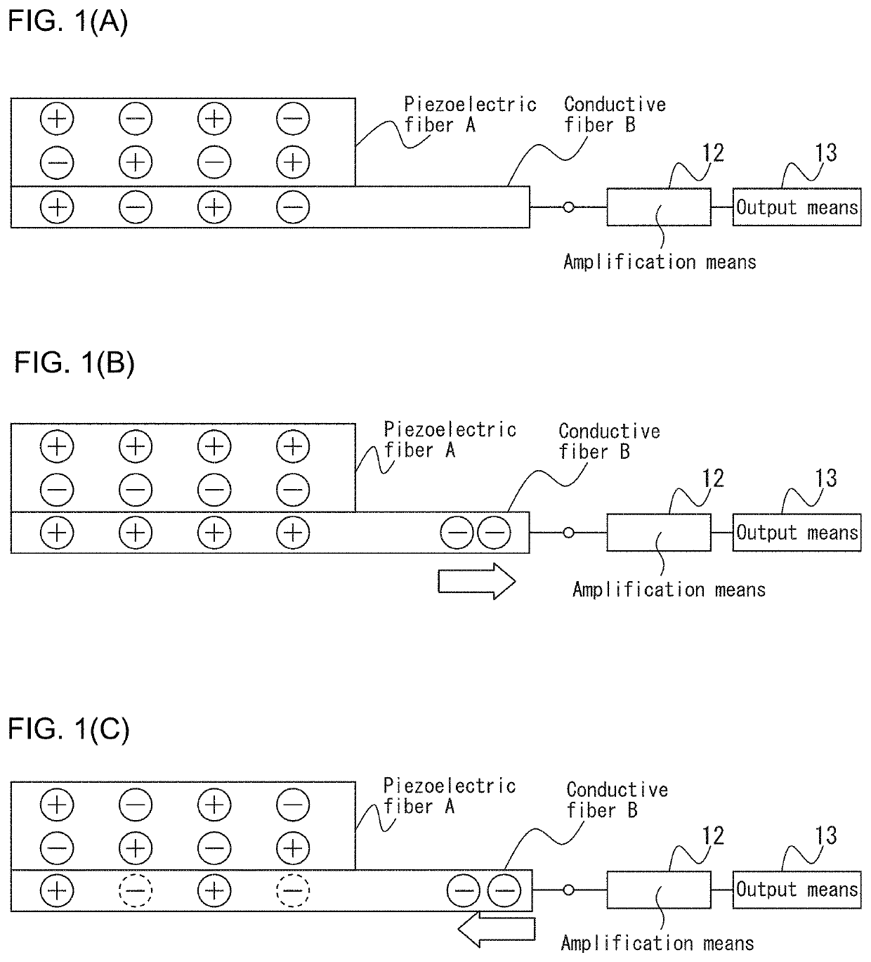
[0117]According to the first invention it is possible to obtain a fiber-like piezoelectric element that allows electrical output to be extracted from the relatively small applied stress of rubbing the surface with a finger or the like. It is also possible to obtain a fiber-like piezoelectric element that can withstand repeated friction on the surface or tip section of the piezoelectric element.
[0118]According to the second invention it is possible to provide a fiber-like piezoelectric element capable of extracting a large electrical signal even by stress produced by relatively small deformation.
[0119]According to the third invention it is possible to provide a fiber-like piezoelectric element capable of extracting a large electrical signal even by stress produced by relatively small deformation, and able to suppress noise signals.
[0120]According to the fourth invention it is possible to obtain a fabric-like transducer with excellent flexibility, by using fiber materials and forming a conventional woven or knitted fabric structure. The transducer of the invention is flexible, and it is therefore possible to obtain a transducer whose input / output are electrical signals, in different forms that allow foldable fabric forms, such as a handkerchief, or wearable fabric forms to be obtained.
[0121]Moreover, according to the fifth invention it is possible to obtain a fabric-like transducer with excellent flexibility, by using fiber materials and forming a conventional woven or knitted fabric structure. The transducer of the invention is flexible, and it is therefore possible to obtain a transducer whose input / output are electrical signals, in different forms that allow foldable fabric forms, such as a handkerchief, or wearable fabric forms to be obtained.

Problems solved by technology

A piezoelectric sheet comprising polylactic acid generates electrical output by shearing stress applied to the sheet, but sufficient electrical output cannot be obtained by tension or compression.
However, PTL 3 discloses absolutely no technology for generating and extracting sufficient electrical output in response to shearing stress by rubbing of fiber surfaces.
Thus, it is extremely difficult to incorporate such a piezoelectric fiber element into a smartphone housing or the like, and extract sufficient electrical output by relatively small amounts of applied stress such as rubbing the surface with a finger or the like.
However, when this fiber-like piezoelectric element is applied for purposes requiring repeated durability, because carbon fiber has weak flexural rigidity, the fiber will gradually break making it impossible to obtain quantitative piezoelectricity, and potentially causing the piezoelectric property to gradually decrease.
In addition, when it is attempted to obtain height or shape information of an object to be measured using a braided piezoelectric element as the contact probe, the carbon fiber breaks and the tip becomes sharper, and the characteristic rigidity of the carbon fiber can potentially damage the surface of the object to be measured.
However, such devices produce the sensation of being worn, and are more desirably in the form of fabrics, i.e. clothing, which are the ultimate wearable form.
The piezoelectric fiber of PTL 4 is an excellent material that can be applied for various purposes, but it cannot always output a high electrical signal in response to stress produced by relatively small amounts of deformation, nor does this publication disclose technology for obtaining a high electrical signal.
However, PTL 3 does not disclose any technology for producing an adequate electrical signal in response to bending or stretching of the piezoelectric fibers, or shearing stress due to rubbing of the surfaces of the piezoelectric fibers.
Therefore, when such piezoelectric fibers are used, it is difficult to extract a sufficient electrical signal simply by stress produced by relatively small amounts of deformation such as rubbing of the surface.
However, because it is still in a sheet form, it has poor flexibility and cannot be used to allow free bending in the manner of a fabric.
However, because they require a separate structure on the surface of a woven or knitted fabric, they are poorly suited for free form surfaces and have poor touch sensation, while also lacking practicality due to problems of manageability, workability and processability.
In addition, a fabric structure formed of a piezoelectric material and a conducting material in the form of a film also exists (PTL 7), but it likewise has poor suitability to free form surfaces and poor touch sensation, and lacks practicality due to problems of manageability, workability and processability.
However, it nowhere suggests higher functions based on selective responses to electrical signals for stress at specific locations or in specific directions, or compositing with piezoelectric units in the thickness direction of the element, and therefore further improvements in this technology have been a topic of interest.
Another issue has been the output of unintended signals during direct contact with the human body or contact with electrified objects.

Method used


Image

  • Piezoelectric element and device using same
  • Piezoelectric element and device using same
  • Piezoelectric element and device using same

Examples


example 1

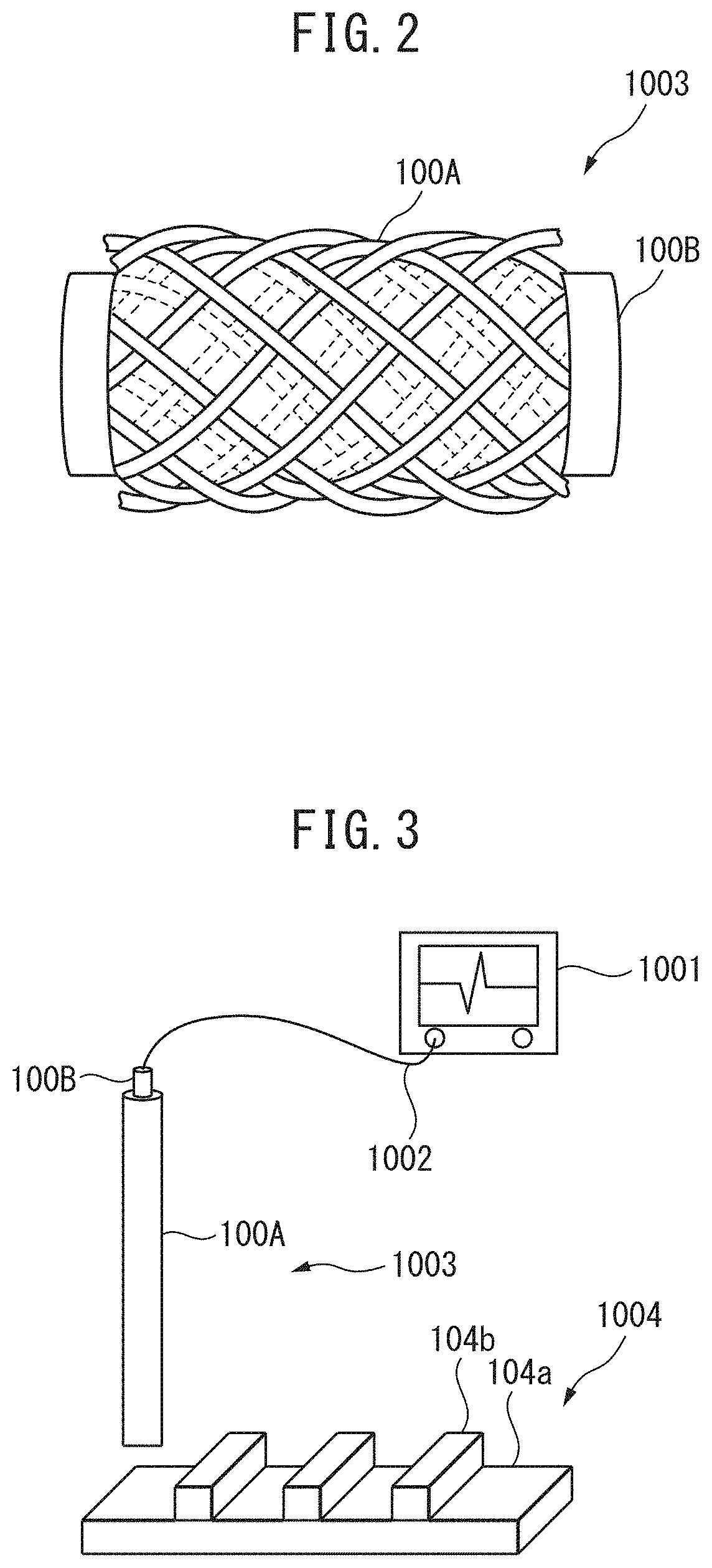
[0663]By wrapping eight piezoelectric fibers 100A while knitting them with the conductive fiber 100B, a braided covered fiber 1003 with a 10 m-long tubular braid was obtained. The silver plated nylon fiber serving as the conductive fiber 100B in the covered fiber 1003 had a volume resistivity of 1.1×10⁻³ Ω·cm. Next, one end of the piezoelectric fibers 100A on the surface of the covered fiber 1003 was removed, leaving the conductive fiber 100B bare, to obtain a piezoelectric element. The piezoelectric element was evaluated its piezoelectric characteristic with the construction as shown in FIG. 3.

[0664]When the top of the measuring sample 1004 was traced with the piezoelectric element, different voltages were confirmed at the base plate 104a section and section where two plates 104a, 104b overlapped.

[0665]Also, the top of the measuring sample 1004 was rubbed 2000 times, and then the piezoelectric characteristic of the piezoelectric element was evaluated, but there was virtually no cha...

example 2

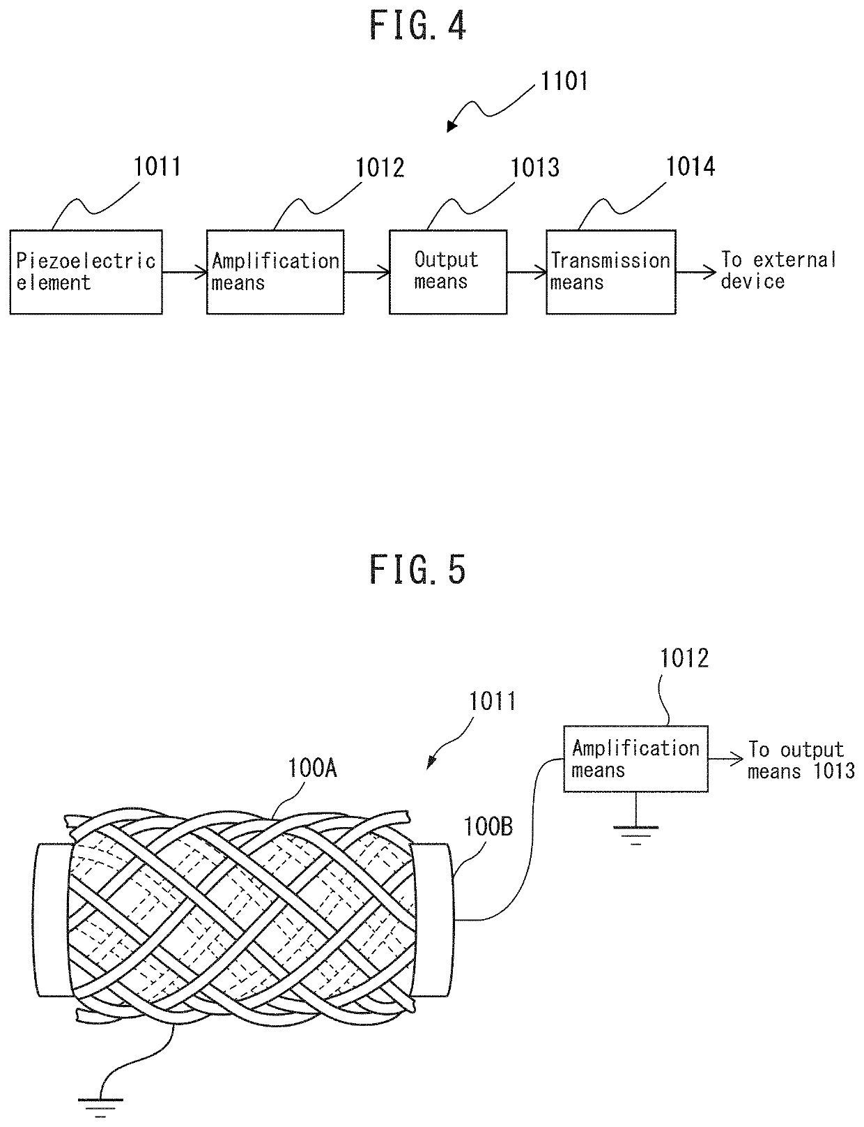
[0681]Using the conductive fiber 200B in the braided piezoelectric element 2001 as a signal wire, an oscilloscope (Digital Oscilloscope DL6000 Series “DL6000”, trade name of Yokogawa Electric Corp.) was connected through the wire via a 1000-fold amplification circuit. The braided piezoelectric element 2001 was bent 90 degrees in an electromagnetic shield box protected by a grounded (earthed) metallic gold net.

[0682]As a result, a difference in potential of approximately 100 mV was detected by the oscilloscope as the output from the braided piezoelectric element 2001, confirming that a sufficiently large electrical signal can be detected by deformation of the braided piezoelectric element 2001.

example 3

[0683]Using the conductive fiber 200B in the braided piezoelectric element 2001 of the fabric-like piezoelectric element 2005 as a signal wire, an oscilloscope (Digital Oscilloscope DL6000 Series “DL6000”, trade name of Yokogawa Electric Corp.) was connected through the wire via a 1000-fold amplification circuit. A conductive fiber 2008 of the weft threads of the fabric-like piezoelectric element 2005 was used as a grounding (earthing) wire for grounding. In this state, the fabric-like piezoelectric element 2005 was bent 90 degrees in the direction perpendicular to the braided piezoelectric element 2001.

[0684]As a result, a virtually noise-free electrical signal was obtained by the oscilloscope, as output from the braided piezoelectric element 2001 of the fabric-like piezoelectric element 2005, and a difference in potential of approximately 100 mV was detected. These results confirmed that it is possible to detect a sufficiently large electrical signal with low noise by deformation ...


PUM

PropertyMeasurementUnit
optical purityaaaaaaaaaa
winding angleaaaaaaaaaa

Abstract

The purpose of the present invention is to provide a fibrous piezoelectric element which enables a large electric signal to be drawn out by stress produced by relatively small deformation. A piezoelectric element includes a braid composed of a conductive fiber and a piezoelectric fiber. In the braid, the conductive fiber is a core, and the piezoelectric fiber is a covering fiber that covers the periphery of the conductive fiber.

Description

CROSS REFERENCE TO RELATED APPLICATIONS[0001]This application is a National Stage of International Application No. PCT / JP2016 / 063479, filed Apr. 28, 2016 (claiming priority based on Japanese Patent Application Nos. 2015-093632, 2015-093687 and 2015-093695, filed Apr. 30, 2015, and Japanese Patent Application Nos. 2015-257491 and 2015-257495, filed Dec. 28, 2015), the contents of which are incorporated herein by reference in their entirety.TECHNICAL FIELD[0002]The present invention relates to a fiber-like piezoelectric element to be used in a touch input device or pointing device, or for surface form measurement or the like. More specifically, it relates to a sensor that can generate sufficient electrical output as a touch sensor merely by rubbing the surface of a fiber-like piezoelectric element, and that can obtain positional information and shape information about an object to be measured, by rubbing the surface of an object to be measured with the fiber-like piezoelectric element...

Claims


Application Information

Patent Timeline
Patent Type & Authority Patents(United States)
IPC IPC(8): H01L41/08G01L1/16H01L41/45H01L41/193D03D1/00H01L41/047G06F3/041H01L41/09H01L41/113H01L41/29
CPCH01L41/082D03D1/0088G01L1/16G06F3/0414H01L41/047H01L41/0986H01L41/1132H01L41/193H01L41/29H01L41/45H10N30/87H10N30/1061H10N30/302H10N30/857H10N30/098H10N30/60H10N30/88H10N30/30H10N30/06H10N30/206
Inventor TAJITSU, YOSHIROONO, YUHEIYAMAMOTO, TOMOYOSHIKANEMATSU, SHUNSUKEYOSHIZAKI, SATOKOOZAWA, SUGURU
Owner TEIJIN FRONTIER CO LTD
Learn More