Eureka AIR delivers breakthrough ideas for toughest innovation challenges, trusted by R&D personnel around the world.

Method and apparatus for enhanced photo-thermal imaging and spectroscopy

a technology of photothermal imaging and spectroscopy, applied in the field of materials investigation or analysis, can solve the problems of insufficient precision of ftir spectroscopy, further degradation of spatial resolution, and inability to achieve the effect of enhancing the spatial resolution

Active Publication Date: 2021-03-09
PHOTOTHERMAL SPECTROSCOPY CORP
View PDF50 Cites 10 Cited by
  • Summary
  • Abstract
  • Description
  • Claims
  • Application Information

AI Technical Summary

Benefits of technology

[0030]“Confocal microscopy” refers to a form of optical microscopy in which the light collected at a detector is confined to light that passes through a small volume within the 3D focus volume of an optical objective on a sample. Confocal microscopy is often performed by placing a “confocal aperture” at a focal plane that is equivalent with the focal plane of the sample, thus blocking stray light that does not pass through the focus volume on the sample.

Problems solved by technology

Practical limitation may degrade this spatial resolution further.
FTIR spectroscopy can be insufficiently precise, and involves significant sample preparation to insure appropriate transmission of the mid-IR beam through the sample, which is not practicable or desirable for many opaque, frangible, or biological substances.
Unfortunately, ATR spectroscopy necessarily requires direct contact of the intervening crystal with the sample which can cause deformation or breaking of the sample, and requires a significant amount of sample preparation, particularly for organic samples.
Raman spectroscopy can achieve resolutions as low as a few hundred nanometers, but usually has a practical limit of 1 micron or more.
Although Raman spectroscopy can achieve resolutions down to several hundred nanometers, the information generated from this approach includes noisy or dispersive artifacts that are inherent in Raman scattering.
Physical restraints on the numerical aperture of a microscope prohibit very large numerical apertures, and therefore the diffraction limit of a microscope depends strongly upon the operating wavelength used for detection, with large wavelengths corresponding to relatively poor resolution and high wavelengths corresponding to increased precision.

Method used


Image

  • Method and apparatus for enhanced photo-thermal imaging and spectroscopy
  • Method and apparatus for enhanced photo-thermal imaging and spectroscopy
  • Method and apparatus for enhanced photo-thermal imaging and spectroscopy

Examples


Embodiment Construction

"d_n">[0058]Dual-Beam Imaging and Spectroscopy

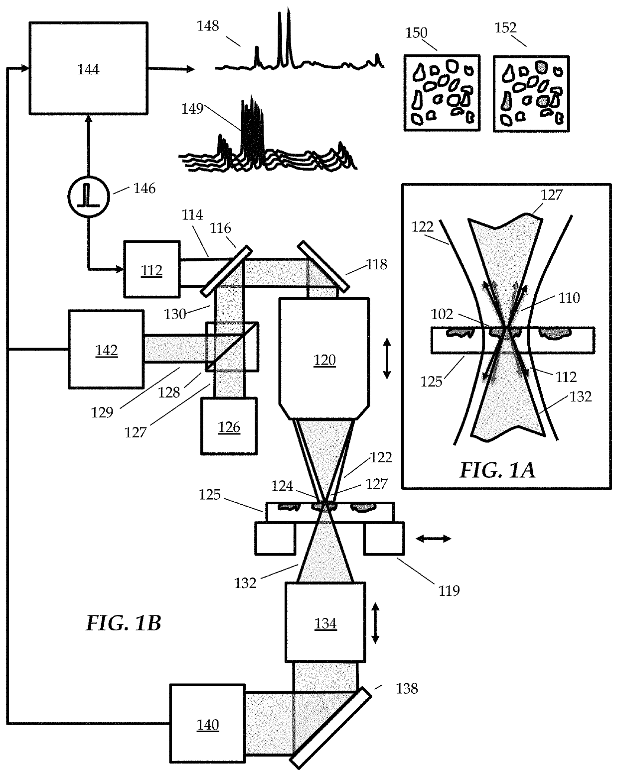
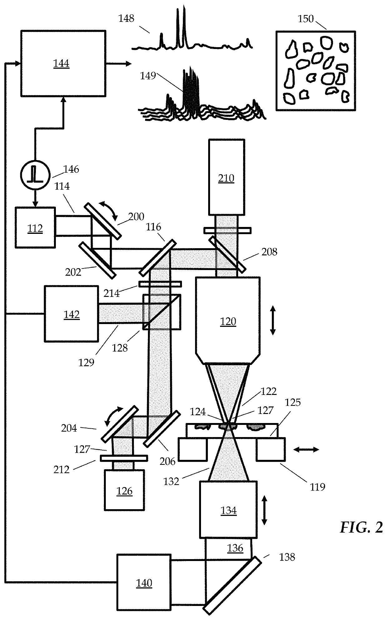
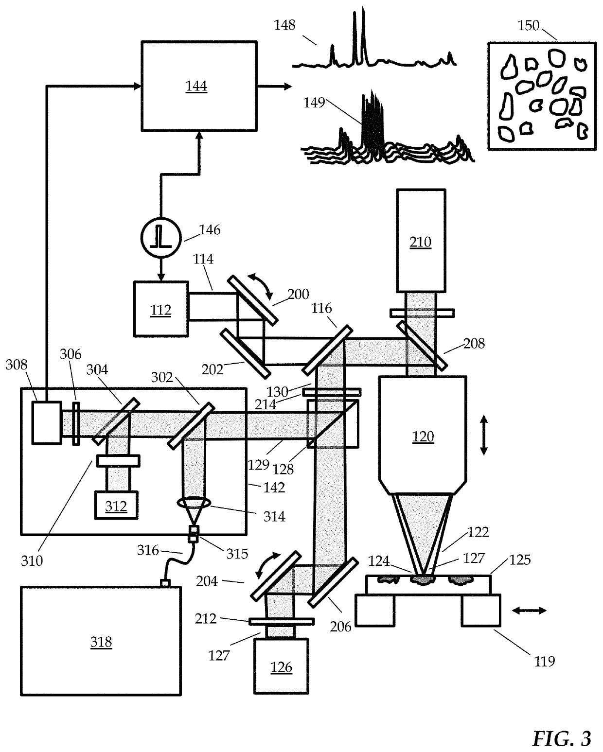
[0059]The current disclosure is directed towards obtaining measurements of optical properties with a dual-beam system. The dual-beam system includes at least one heating beam, and at least one sensing beam. The two beams are directed towards a sample of material and data corresponding to that sample is collected at a resolution that is smaller than the diffraction limit of the heating beam. In embodiments, infrared absorption spectrum of a sample can be sensed with submicron scale resolution, and in some embodiments additional, complementary measurement techniques can also be used simultaneously or in parallel. FIG. 1A shows a simplified conceptual diagram of a principle of high resolution photo-thermal detection of infrared absorption. An infrared (IR) heating beam 122 is directed at a region of interest 102 of a sample 125. If the IR light beam is tuned to a wavelength where the sample absorbs IR light, for example associated with a mo...


PUM

PropertyMeasurementUnit
wavelength rangeaaaaaaaaaa
wavelengthsaaaaaaaaaa
wavelengthaaaaaaaaaa

Abstract

System for performing chemical spectroscopy on samples from the scale of nanometers to millimeters or more with a multifunctional platform combining analytical and imaging techniques including dual beam photo-thermal spectroscopy with confocal microscopy, Raman spectroscopy, fluorescence detection, various vacuum analytical techniques and / or mass spectrometry. In embodiments described herein, the light beams of a dual-beam system are used for heating and sensing.

Description

RELATED APPLICATION[0001]This application claims the benefit of U.S. Provisional Application No. 62 / 569,944 filed Oct. 9, 2017, which is hereby fully incorporated herein by reference.PRIORITY[0002]Various aspects of the embodiments and techniques described in this application are described in U.S. Provisional Applications, Ser. Nos. 62 / 427,671, filed Nov. 29, 2016, 62 / 469,349, filed Mar. 9, 2017, 62 / 505,533, filed May 12, 2017, and 62 / 541,749, filed Aug. 6, 2017, the disclosures of each of which are hereby incorporated by reference.BACKGROUND1. Field of the Invention[0003]The specification relates to investigating or analyzing materials by the use of optical means, i.e. using infra-red, visible, or ultraviolet light. Embodiments described herein relate to imaging and spectroscopy, and, more particularly, to enhancements to photo-thermal imaging and spectroscopy systems and techniques for acquiring spectral information indicative of the optical properties and / or material / chemical com...

Claims


Application Information

Patent Timeline
Patent Type & Authority Patents(United States)
IPC IPC(8): G01N21/35G01N21/65G01N21/59H01J37/26G01N23/20091G01N23/207G01N21/552G01N21/17G01N21/3563H01J49/26G01N21/47G01N21/64
CPCG01N21/35G01N21/171G01N21/1717G01N21/3563G01N21/552G01N21/59G01N21/65G01N23/207G01N23/20091H01J37/26G01N21/6458G01N2021/1725G01N2021/1731G01N2021/479H01J49/26H01J37/226
Inventor PRATER, CRAIGKJOLLER, KEVINSHETTY, ROSHAN
Owner PHOTOTHERMAL SPECTROSCOPY CORP
Why Eureka
Eureka Blog
Learn More