
Antenna assembly

a technology of antenna and assembly, applied in the field of electronic devices, can solve the problems of increasing the complexity and/or size of portable electronic devices, increasing the difficulty of integrating various functional components without unduly degrading their performance or increasing costs, and reducing the width of flexible circuits. , the effect of increasing the size of the signal pad

Active Publication Date: 2021-03-02
APPLE INC
View PDF7 Cites 0 Cited by
  • Summary
  • Abstract
  • Description
  • Claims
  • Application Information

AI Technical Summary

Benefits of technology

The patent describes an electronic device with a flexible antenna structure that is attached to a larger flexible circuit panel. The attachment region of the flexible circuits includes ground pads to reduce signal loss and a temperature-sensitive adhesive for mechanical robustness. The antenna assembly can be included in the electronic device. The technical effect of this design is improved signal quality and durability of the antenna assembly in electronic devices.

Problems solved by technology

As portable electronic devices increase in complexity and / or decrease in size, it becomes increasingly challenging to integrate various functional components without unduly degrading their performance or increasing cost.

Method used


Image

  • Antenna assembly
  • Antenna assembly
  • Antenna assembly

Examples


Embodiment Construction

[0023]The detailed description set forth below is intended as a description of various implementations and is not intended to represent the only implementations in which the subject technology may be practiced. As those skilled in the art would realize, the described implementations may be modified in various different ways, all without departing from the scope of the present disclosure. Accordingly, the drawings and description are to be regarded as illustrative in nature and not restrictive.

BRIEF SUMMARY

[0024]Embodiments of the present disclosure include an antenna assembly comprising: a first flexible circuit having a first signal line, at least one first shielding layer, and a first attachment region, wherein the first attachment region includes a first signal pad and first shielding pads disposed around the first signal pad; and a second flexible circuit having a second signal line, at least one second shielding layer, and a second attachment region, the second attachment regio...


PUM


Abstract

A disclosed antenna assembly includes a first flexible circuit having a first signal line, at least one first shielding layer, and a first attachment region. The first attachment region includes a first signal pad and first shielding pads disposed around the first signal pad. The antenna assembly further includes a second flexible circuit having a second signal line, at least one second shielding layer, and a second attachment region. The second attachment region includes a second signal pad and second shielding pads disposed around the second signal pad. The first attachment region is attached to the second attachment region.

Description

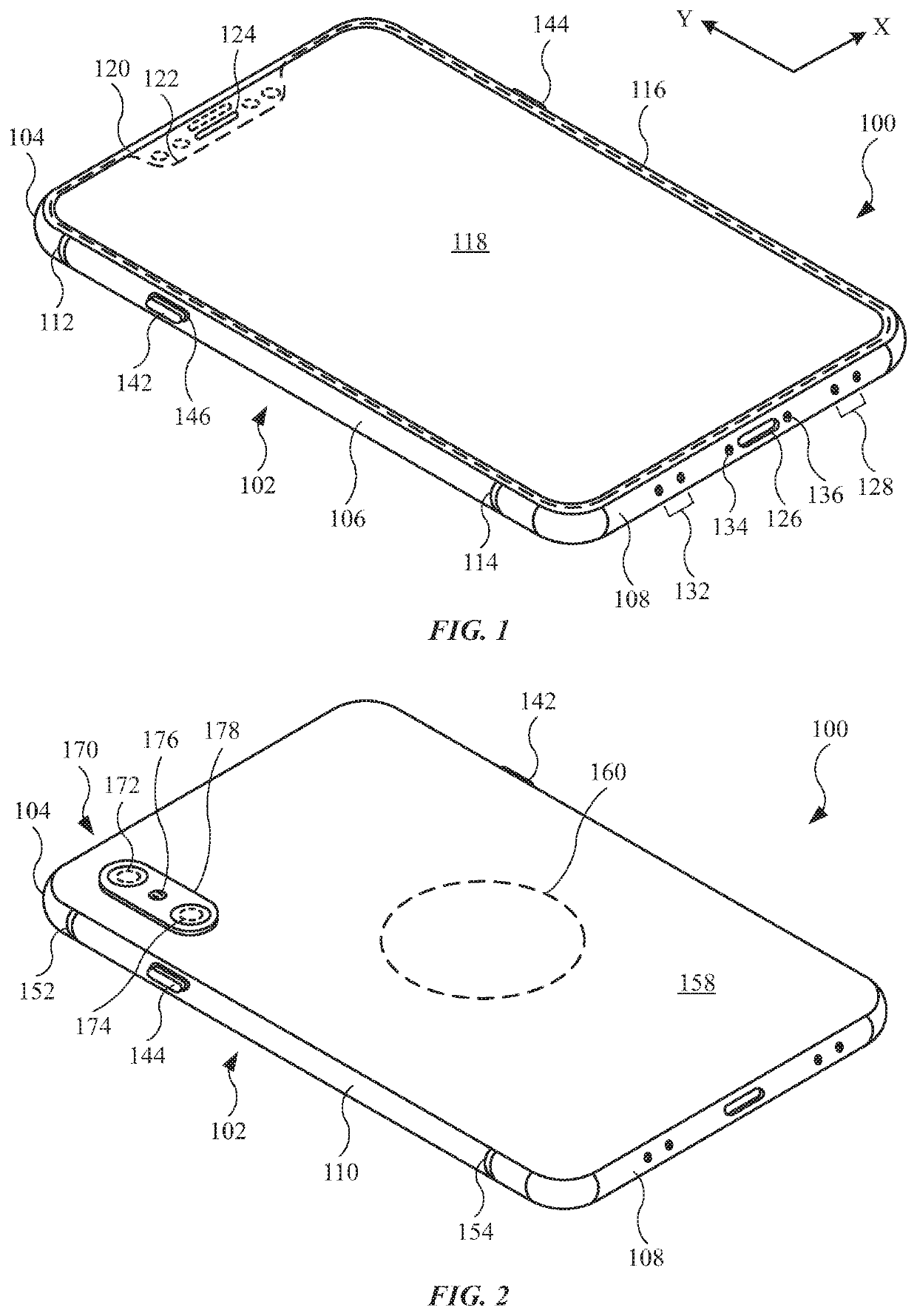
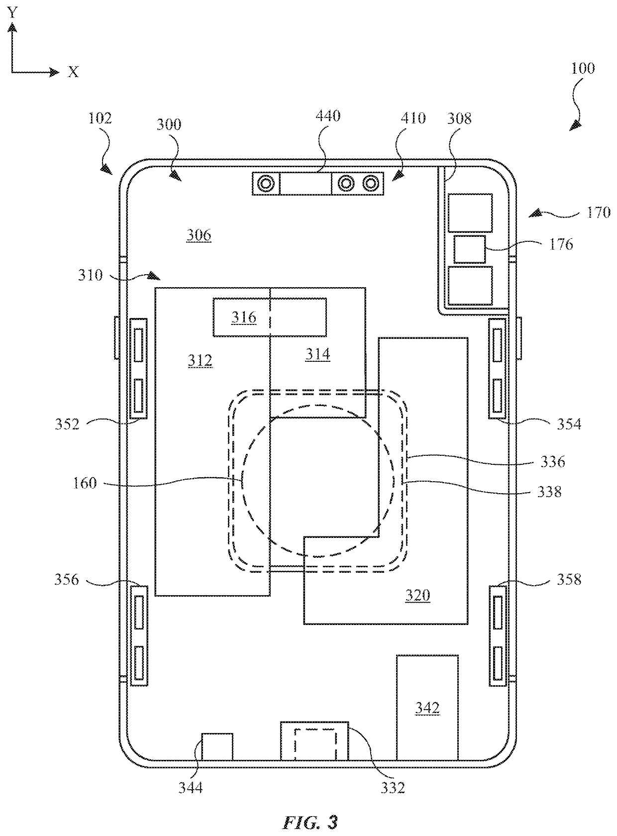
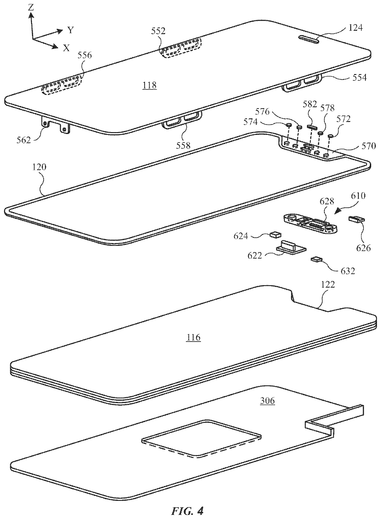
CROSS REFERENCE TO RELATED APPLICATIONS[0001]This application claims the benefit of U.S. Provisional Application No. 62 / 730,485, entitled “ANTENNA ASSEMBLY,” filed Sep. 12, 2018, the entirety of which is incorporated herein by reference.TECHNICAL FIELD[0002]The present description relates generally to an electronic device, and, more particularly, to an antenna assembly having multiple flexible circuits.BACKGROUND[0003]Portable electronic devices are known to include a housing and a cover glass that combines with the housing to enclose components such as a circuit board, a display, and a battery. Also, portable electronic devices are known to communicate over a network server to send and receive information, as well as communicate with a network carrier to send and receive voice communication. As portable electronic devices increase in complexity and / or decrease in size, it becomes increasingly challenging to integrate various functional components without unduly degrading their perf...

Claims


Application Information

Patent Timeline
Patent Type & Authority Patents(United States)
IPC IPC(8): H01Q1/24H05K1/02H05K1/03H05K1/18H01Q1/22
CPCH01Q1/243H01Q1/2283H05K1/0219H05K1/0298H05K1/0393H05K1/189H05K2201/0715
Inventor JIN, NANBOMONACO, DEVON A.PARR, DONALD J.TONG, ERICA J.WANG, HAN
Owner APPLE INC
Learn More