
Hypocycloid compressor

a compressor and hypercycloid technology, applied in the field of compressors, can solve the problems of affecting the operation of the electric motor, not working well with the electric motor, and relatively high peak torque of the common type of compressor, and achieves smooth torque profile, high speed, and smooth operation.

Active Publication Date: 2021-02-16
BENDIX COMML VEHICLE SYST LLC
View PDF25 Cites 0 Cited by
  • Summary
  • Abstract
  • Description
  • Claims
  • Application Information

AI Technical Summary

Benefits of technology

The compressor described in this patent is better than regular compressors because it has a smooth torque profile and can run smoothly at high speeds. It also reduces fluid leakage and is more efficient than regular rotary compressors. This allows for the use of electric motors to drive the compressor.

Problems solved by technology

Some common types of compressors, however, do not work well with electric motors.
In particular, a typical positive displacement, reciprocating single or dual cylinder compressor has a relatively high peak torque and a significant rotational imbalance that can negatively affect the operation of the electric motor.
A typical rotary compressor has improved rotational balance, but is relatively inefficient due to leakage past the vanes of the compressor.

Method used


Image

  • Hypocycloid compressor
  • Hypocycloid compressor
  • Hypocycloid compressor

Examples


Embodiment Construction

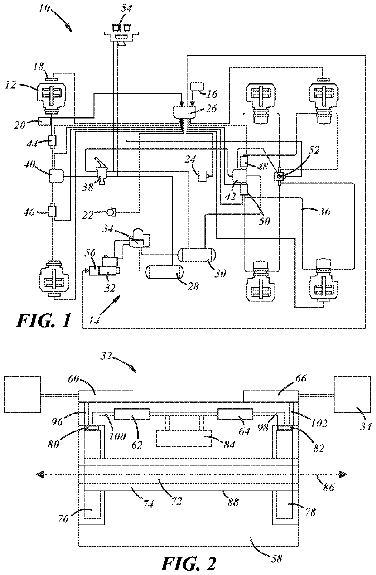
[0016]Referring now to the drawings wherein like reference numerals are used to identify identical components in the various views, FIG. 1 illustrates a braking system 10 configured to brakes wheels on a vehicle in order to slow or stop movement of the vehicle. In the illustrated embodiment, the vehicle comprises a tractor of a tractor-trailer. It should be understood, however, that the braking system disclosed herein could be used to control wheel brakes in a wide variety of vehicles. Further, although the illustrated embodiment shows system 10 as applied to control wheel brakes in the tractor of a tractor-trailer, it should be understood that system 10 could be configured to control wheel brakes in the trailer as well. System 10 may be configured to communicate with other vehicle systems over a conventional vehicle communication bus such as a controller area network (CAN) (or another communication medium such as power line communication (PLC)) including, for example, advanced driv...


PUM


Abstract

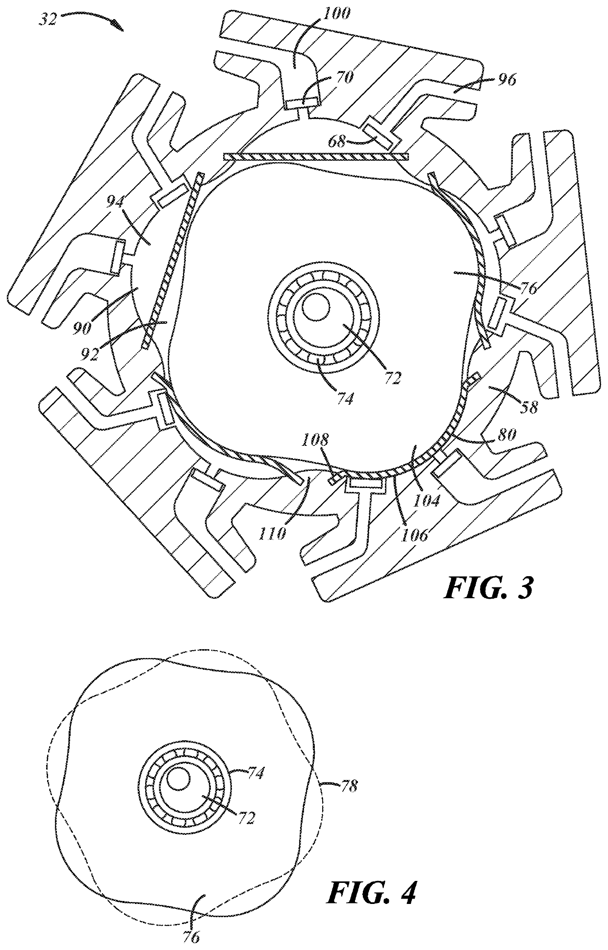
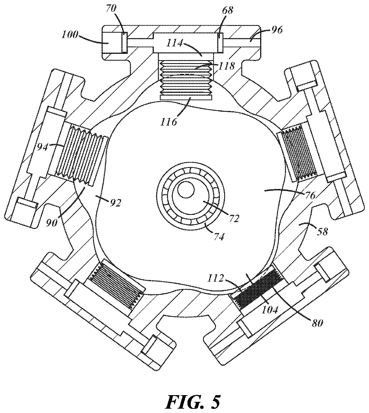
A compressor includes a stationary housing disposed about a central axis and having a radially inner surface defining a plurality of circumferentially spaced cavities opening into an interior space of the housing. The compressor further includes a plurality of fluid volume control members, each of which is disposed within one of the plurality of cavities and defines a fluid chamber within the cavity sealed relative to the interior space. An eccentric shaft is disposed within the interior space of the housing and configured for rotation about the central axis. A hypocycloid rotor is disposed within the interior space of the housing and supported on the eccentric shaft. The rotor defines a plurality of lobes configured for movement into and out of each cavity responsive to rotation of the shaft to displace the fluid volume control member in each cavity and adjust a volume of each fluid chamber.

Description

BACKGROUND OF THE INVENTIONa. Field of the Invention[0001]This invention relates to a compressor used in vehicle brake systems. In particular, this invention relates to a compressor that generates a relatively smooth torque profile and has a relatively high efficiency to facilitate use with an electric motor.b. Background Art[0002]Conventional vehicles commonly include wheel brakes at each wheel on the vehicle that are activated by fluid pressure. A fluid control circuit on the vehicle includes a compressor that draws in outside air and compresses the air, a fluid reservoir that stores the compressed air and a plurality of electronically or pneumatically controlled valves that control delivery of the pressurized fluid from the fluid reservoir to the wheel brakes. Increasing use of electricity to provide power within vehicles has led to the use of electric motors to drive the compressor. Some common types of compressors, however, do not work well with electric motors. In particular, ...

Claims


Application Information

Patent Timeline
Patent Type & Authority Patents(United States)
IPC IPC(8): F04B27/053F04B39/06F04B45/02F04B45/04
CPCF04B27/053F04B39/06F04B45/022F04B45/043F04B1/0413F04B9/045F04B27/0414F04B35/01F04B43/0045F04B43/026
Inventor COLAVINCENZO, DAVID D.
Owner BENDIX COMML VEHICLE SYST LLC
Learn More