
Image-generation device for a head-up display and method for controlling such a device

a head-up display and image-generation technology, applied in the direction of projectors, vehicle components, instruments, etc., can solve the problems of significant electrical energy consumption of the head-up display, and achieve the effect of reducing the amount of electrical energy consumed

Active Publication Date: 2021-01-26
VALEO COMFORT & DRIVING ASSISTANCE
View PDF7 Cites 0 Cited by
  • Summary
  • Abstract
  • Description
  • Claims
  • Application Information

AI Technical Summary

Benefits of technology

This patent aims to reduce the electricity usage of a light source and minimize the light halo on a combiner, which can cause glare. The invention includes a curved plate that can act as an image enlarger, which can be a fold back mirror, a combiner, or even a windshield with a combiner function. These technical effects can be used in a projection system.

Problems solved by technology

Such a head-up display has the major drawback of significant electrical energy consumption.
Another drawback is that the blocking by the screen of the light emitted by the backlighting device is not totally effective, so that a light halo can be observed on all of the combiner (called “postcard effect”) which is at least not esthetically pleasing, and even a nuisance for the driver.

Method used


Image

  • Image-generation device for a head-up display and method for controlling such a device
  • Image-generation device for a head-up display and method for controlling such a device

Examples


Embodiment Construction

[0033]The following description with respect to the attached drawings, given as nonlimiting examples, will give a good understanding of what the invention consists of and how it can be produced.

[0034]In the attached drawings:

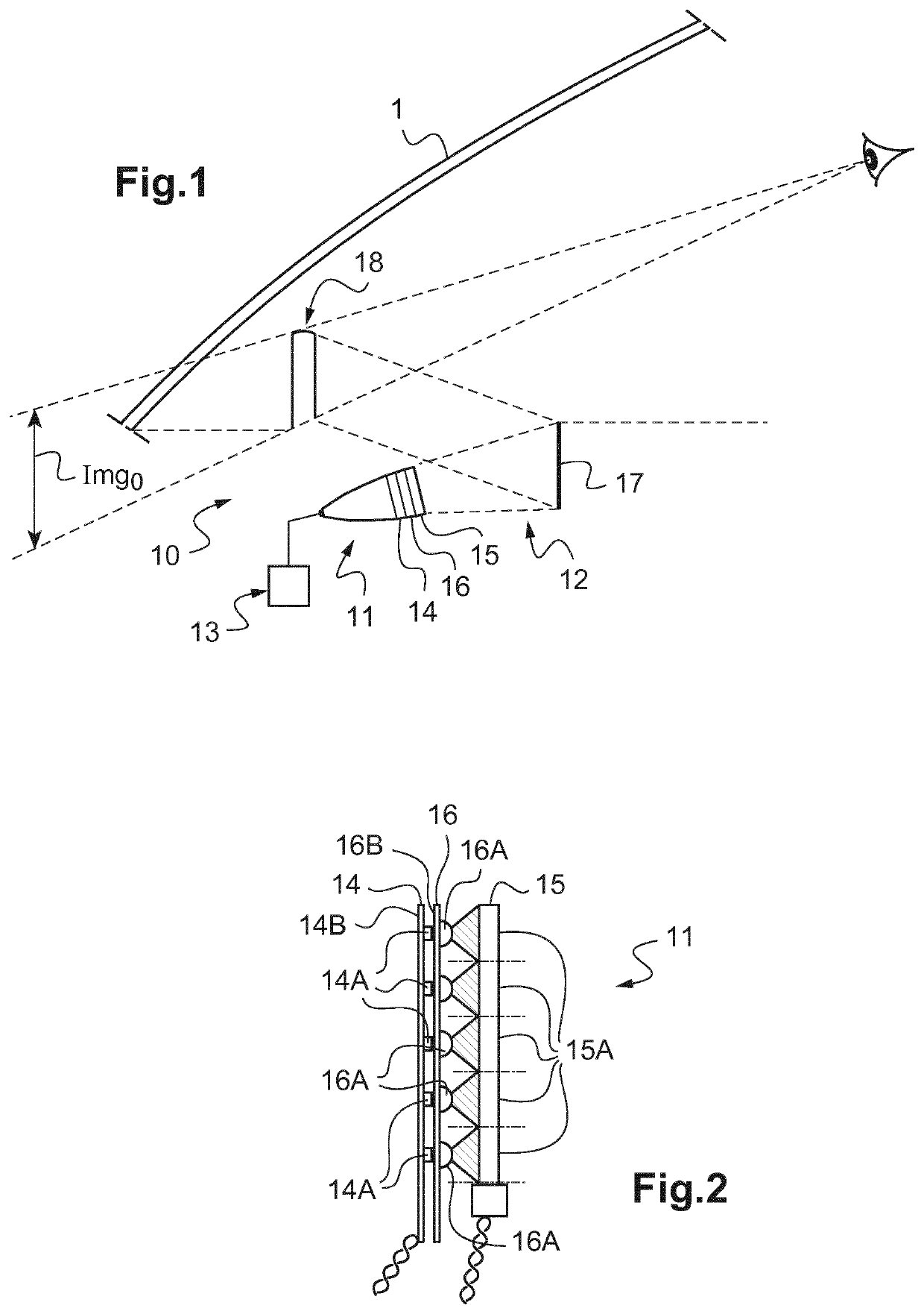
[0035]FIG. 1 is a schematic view of a head-up display of a motor vehicle, according to the invention;

[0036]FIG. 2 is a schematic view of a part of the image-generating device of the head-up display of FIG. 1;

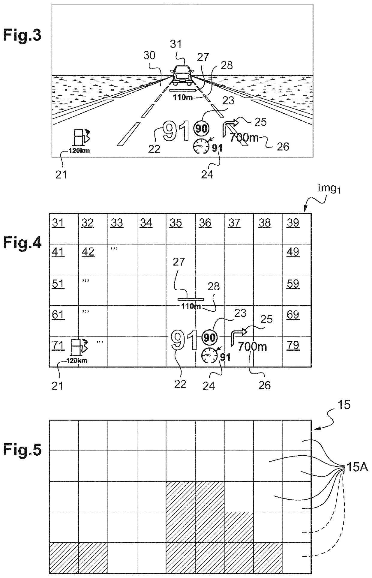
[0037]FIG. 3 is a schematic view of an image generated by the head-up display of FIG. 1, as it is seen by a driver, superimposed on the road that the motor vehicle is taking;

[0038]FIG. 4 is a schematic view of the image of FIG. 3, on which a grid is superimposed; and

[0039]FIG. 5 represents the grid of FIG. 4.

[0040]FIG. 1 shows a head-up display 10 intended for a vehicle, for example a motor vehicle.

[0041]This head-up display 10 comprises an image-generating device 11 and an optical projection assembly 12 that makes it possible to project the image generated ...


PUM

PropertyMeasurementUnit
light intensityaaaaaaaaaa
light intensitiesaaaaaaaaaa
heightaaaaaaaaaa

Abstract

The invention relates to an image-generation device (11) for a head-up display (10), comprising: a light source, a light modulator suitable for spatially modulating the light emitted by the light source, and a computer (13) suitable for controlling the light of source and the light modulator such that they generate an image. According to the invention, the light source is composed of a plurality of separate light elements, and the computer is able to modulate the light intensity emitted by each light element independently of the light intensity emitted by the other light elements.

Description

TECHNICAL FIELD TO WHICH THE INVENTION RELATES[0001]The present invention relates generally to motor vehicle driving aid devices.[0002]It relates more particularly to an image-generating device for head-up display, comprising:[0003]a light source,[0004]a light modulator adapted to spatially modulate the light emitted by the light source, and[0005]a computer adapted to control the light source and the light modulator so that they generate an image.[0006]It relates also to a method for controlling such a device.TECHNOLOGICAL BACKGROUND[0007]To facilitate and make the driving of a motor vehicle safer, it is desirable to avoid having the driver be forced to divert his or her gaze from the road that he or she is taking.[0008]For that, it is known practice to use a head-up display, adapted to project outside of the vehicle information (vehicle speed, direction to be followed, malfunctioning of the engine, presence of obstacle, etc.) at the height of the gaze of the driver.[0009]Various he...

Claims


Application Information

Patent Timeline
Patent Type & Authority Patents(United States)
IPC IPC(8): G02B27/01B60K35/00G02F1/13357G03B21/20
CPCG02B27/0101B60K35/00G02F1/133603G03B21/2006G02F2001/133613G02B27/01B60K35/90B60K35/23B60K35/21B60K35/80B60K35/60B60K35/22G02F1/133613
Inventor IRZYK, MICHAEL
Owner VALEO COMFORT & DRIVING ASSISTANCE
Learn More