Neutron capture therapy system
a neutron capture and therapy technology, applied in the field of neutron capture therapy system, can solve the problems of many normal tissues on the beam path being damaged, tumor cells being exposed to radioactive rays, physical restrictions of conventional photon or electron therapy, etc., and achieve the effect of enhancing the intensity of epithermal neutron beam
- Summary
- Abstract
- Description
- Claims
- Application Information
AI Technical Summary
Benefits of technology
Problems solved by technology
Method used
Image
Examples
first embodiment
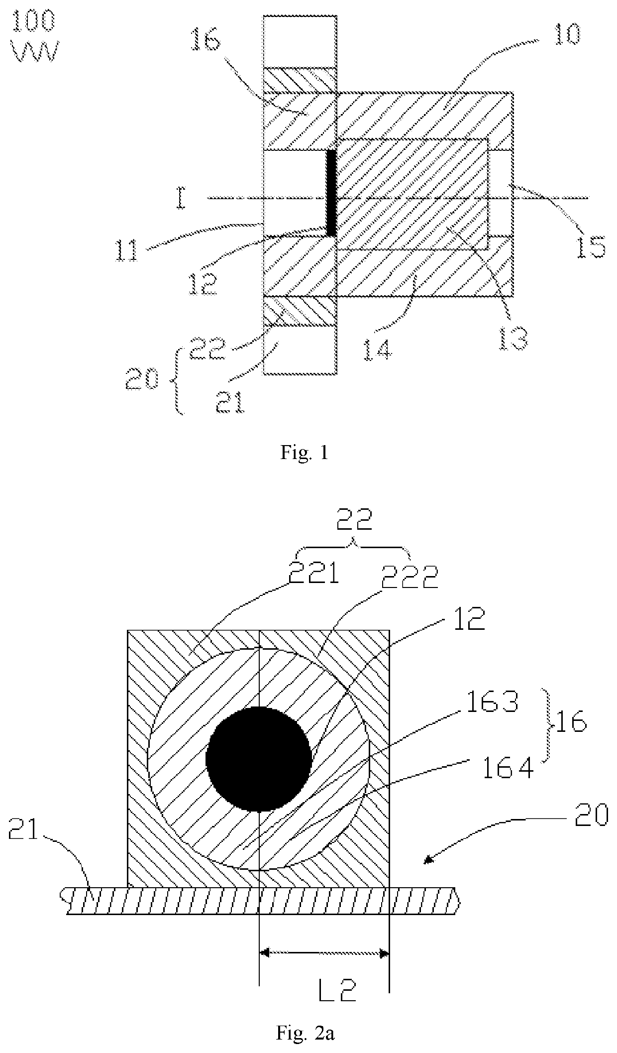
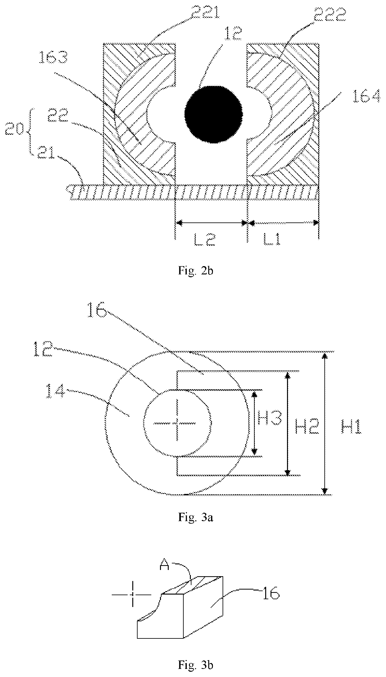
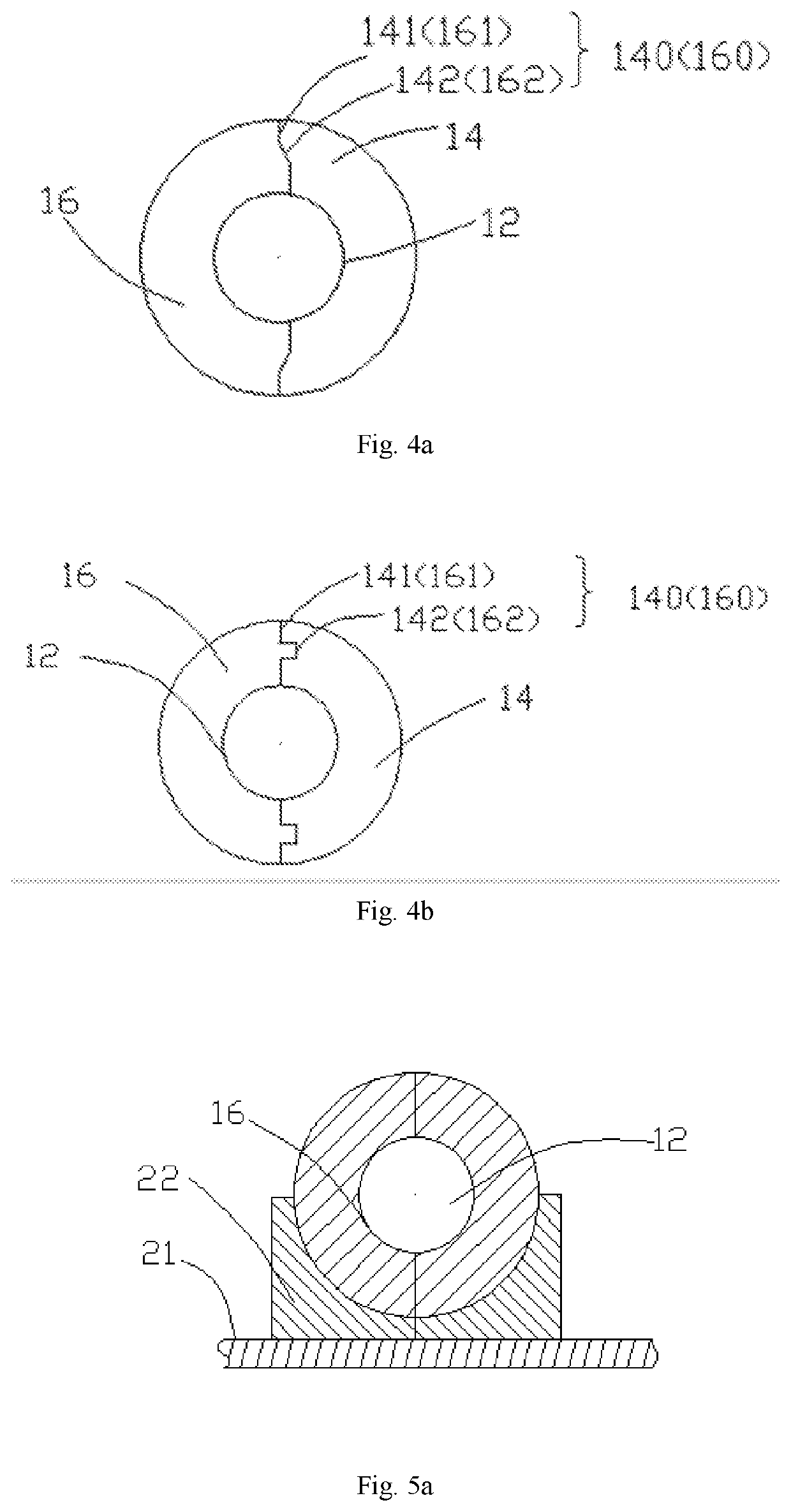
[0055]the present disclosure is also shown in FIG. 2a and FIG. 2b, and is described based on the reflector 14 provided with the two movable members 16 (namely a first movable member 163 and a second movable member 164) located on the two sides of the neutron generator 12 and mutually connected. The driving assembly 20 includes a guide rail 21 arranged outside the beam shaping assembly 10 and gates 22 used for supporting the movable members 16, and the gates22 move in the guide rail 21 to drive the movable members 16 to move away from or close to the neutron generator 12. The movable members 16 include the first movable member 163 and the second movable member 164, the gates 22 include a first gate 221 and a second gate 222 which can move along the guide rail 21, the first gate 221 supports the first movable member 163, and the second gate 222 supports the second movable member 164. The first gate 221 and the second gate 222 move in the guide rail 21 to drive the first movable member...
second embodiment
[0058]FIG. 6 is a schematic view of the present disclosure. A driving assembly 20 includes a rotating member 24 (such as a shaft) and gates 22′ fixedly held to the rotating member 24. The rotating member 24 is located under a beam shaping assembly 10, and an axis of the rotating member 24 is parallel to that of a neutron generator 12. The gates 22′ rotate up and down around the rotating member 24. When the gates 22′ move downwards, the gates 22′ drive movable members 16 to move away from the neutron generator 12, the neutron generator 12 is exposed out, and the neutron generator 12 can be replaced; and when the gates 22′ rotate upwards, the gates 22′ drive the movable members 16 to move close to the neutron generator 12, and the movable members 16 surround the neutron generator 12, and is used for leading the deflected neutrons back in the subsequent neutron capture therapy process.
third embodiment
[0059]FIG. 7 is a schematic view of the present disclosure. A driving assembly 20 in the present embodiment includes first connecting rods 25 fixed to the outside of the beam shaping assembly 10, second connecting rods 26 connected to movable members 16, and third connecting rods 27 enable the first connecting rods 25 and the second connecting rods 26 to be connected, the third connecting rods 27 move to drive the second connecting rods 26 to move, and the movable members 16 move away from or close to the neutron generator 12 as the second connecting rods 26 move.
[0060]FIG. 8 is a schematic view of a fourth embodiment of the present disclosure. When the second linear height H2 of movable members 16 is smaller than a first linear height H1 of the reflector 14 (particularly when the second linear height H2 of the movable members 16 is smaller than a third linear height H3 of a neutron generator 12), the guide rail 28 can be arranged in the reflector 14, and handles 165 can be arranged...
PUM
 Abstract
Description
Claims
Application Information
 - R&D
- Intellectual Property
- Life Sciences
- Materials
- Tech Scout
- Unparalleled Data Quality
- Higher Quality Content
- 60% Fewer Hallucinations
Browse by: Latest US Patents, China's latest patents, Technical Efficacy Thesaurus, Application Domain, Technology Topic, Popular Technical Reports.
© 2025 PatSnap. All rights reserved.Legal|Privacy policy|Modern Slavery Act Transparency Statement|Sitemap|About US| Contact US: help@patsnap.com


