
Liquid crystal composition and liquid crystal display element or display thereof

a liquid crystal composition and liquid crystal display technology, applied in liquid crystal compositions, instruments, chemistry apparatus and processes, etc., can solve the problems of narrow viewing angle, significant inferior image sticking level, and imperfect liquid crystal medium used for display elements of active matrix addressing modes such as va modes in themselves, so as to modulate the transmission and blocking of light, excellent regular alignment characteristics

Active Publication Date: 2020-12-08
SHIJIAZHUANG CHENGZHI YONGHUA DISPLAY MATERIALS CO LTD
View PDF2 Cites 1 Cited by
  • Summary
  • Abstract
  • Description
  • Claims
  • Application Information

AI Technical Summary

Benefits of technology

The present invention provides a special liquid crystal material that has good alignment and can control the transmission and blocking of light in a liquid crystal display. This is achieved by using a special force called the van der Waals force between the liquid crystal molecules.

Problems solved by technology

In the early commercialized TFT-LCD products the TN display mode is substantially used, and the largest problem is the narrow viewing angle.
However, the liquid crystal medium used for display elements of an active matrix addressing mode such as the VA mode in itself is not perfect and has disadvantages, for example, an image sticking level which is significantly inferior to that of a positive dielectric anisotropic display element, a slower response time, a higher driving voltage, etc.
Additionally, although the entire liquid crystal has a pretilt angle and no domino delay, and a faster response time can be obtained while maintaining the same driving voltage without affecting the image sticking level, since the electrodes are densely distributed in the Fine Slit in the pixels, if the electrode widths are not uniformly distributed, problems with uneven display may easily occur.

Method used


Image

  • Liquid crystal composition and liquid crystal display element or display thereof
  • Liquid crystal composition and liquid crystal display element or display thereof
  • Liquid crystal composition and liquid crystal display element or display thereof

Examples


Embodiment Construction

[0044]The present invention is further described in detail by combining the following specific examples, but the present invention is not limited to the following examples. The methods are all conventional methods unless otherwise specified. The raw materials can be obtained from public commercial routes unless otherwise specified. The percentages are all percentages by mass unless otherwise specified.

[0045]In the following examples,

[0046]CP represents a clearing point and is directly measured using a WRX-1S microscopic thermal analyzer, and the heating rate is set to 3° C. / min.

[0047]Δn represents an optical anisotropy (589 nm, 20° C.),

[0048]Δε represents a dielectric anisotropy (25° C., 1 KHz, HP4284A, a 5.2 microns TN left-hand cell),

[0049]γ1 represents a rotary viscosity (mpas) at 20° C., VHR (%) represents a charge holding ratio (5 V, 60 Hz, 20° C.), and ρ (×1013 Ω·cm) represents a resistivity (20° C.),

[0050]k33 represents a bend elastic constant

[0051]τ represents a response tim...


PUM

PropertyMeasurementUnit
temperatureaaaaaaaaaa
resistivityaaaaaaaaaa
dielectricaaaaaaaaaa

Abstract

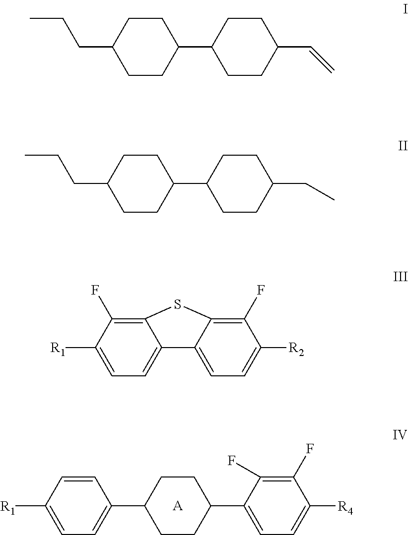
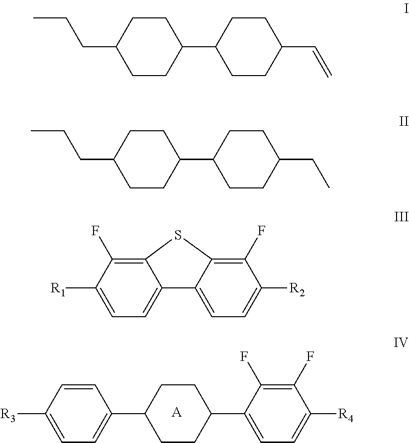
The present invention discloses a negative dielectric anisotropic liquid crystal composition, characterized in that the liquid crystal composition comprises one or more compounds represented by formula I, one or more compounds represented by formula II, one or more compounds represented by formula III and one or more compounds represented by formula IV,In the liquid crystal molecules of the composition, the van der Waals force therebetween is used as a motive force, such that the liquid crystal molecules generate an attractive force at an appropriate distance and positional relationships, thereby enabling the liquid crystal molecules to have excellent regular alignment characteristics, which is favorable for the liquid crystal molecules to modulate the transmission and blocking of light in the liquid crystal display device.

Description

TECHNICAL FIELD[0001]The present invention belongs to the field of liquid crystal display, and specifically relates to a liquid crystal composition and a liquid crystal display element or a liquid crystal display comprising the liquid crystal composition.BACKGROUND ART[0002]Thin film transistor liquid crystal display (TFT-LCD) has undergone a long period of basic research. After achieving mass production and commercialization, it has become a mainstream product in LCD applications due to its advantages of a light weight, being environmentally friendly, high performance, etc.: it can be seen that TFT-LCDs can be used everywhere whether in small-sized mobile phone screens, or large-sized notebooks (Notebook PCs) or monitors (Monitors), and large-scale liquid crystal display televisions (LCD-TV).[0003]In the early commercialized TFT-LCD products the TN display mode is substantially used, and the largest problem is the narrow viewing angle. With the increase of the product size, especia...

Claims


Application Information

Patent Timeline
Patent Type & Authority Patents(United States)
IPC IPC(8): G02F1/1333C09K19/34G02F1/137G02F1/1368C09K19/30C09K19/12
CPCG02F1/137C09K19/3491C09K2019/3016C09K2019/3004C09K2019/123G02F1/1368C09K2019/3027G02F2001/13712C09K2019/301C09K19/44G02F1/13712
Inventor WANG, MINGXIAZHANG, XINGWANG, HUIFANGWANG, GUOFANGCHENG, JIANMINGSHAO, ZHEYUN, GUOLIANG
Owner SHIJIAZHUANG CHENGZHI YONGHUA DISPLAY MATERIALS CO LTD
Learn More