
Auto injector with cartridge retention system

a cartridge retention and auto-injector technology, applied in the field of auto-injector with cartridge retention system, can solve the problems of preventing self-administration use, cumbersome use of front-loaded drug delivery system, and high risk of being injured, and achieves convenient front-loading, no increased risk of being injured, and maintaining the position of the cartridg

Active Publication Date: 2020-11-17
ASCENDIS PHARM AS
View PDF7 Cites 10 Cited by
  • Summary
  • Abstract
  • Description
  • Claims
  • Application Information

AI Technical Summary

Benefits of technology

The cartridge assembly is designed to be inserted by a human being with a force sufficient to overcome the spring-load acting on the assembly. The assembly is moved outwards at an angular position where the cartridge retention member and the guide members prevent it from falling out. The design also includes cut-outs with edges along and along the longitudinal axis, which help improve the engagement between the ejector rod and the lock when the stop is engaged. The technical effects of this design are improved stability and secure engagement of the cartridge assembly with the ejector and lock.

Problems solved by technology

However, these front-loaded drug delivery systems are cumbersome to use since they require that a user uses two hands for the operation of loading the drug delivery system with a cartridge since one hand is needed to hold the device and another is needed to insert and rotate the cartridge.
For at least some groups of users this may prevent self-administration use or make own use very cumbersome.
The riser portion prevents or at least reduces the risk that a direction of rotation is suddenly reversed during insertion of the cartridge assembly whereby retention may fail and lead to an unsatisfactory user experience.

Method used


Image

  • Auto injector with cartridge retention system
  • Auto injector with cartridge retention system
  • Auto injector with cartridge retention system

Examples


Embodiment Construction

[0097]Various embodiments are described hereinafter with reference to the figures. Like reference numerals refer to like elements throughout. Like elements will, thus, not be described in detail with respect to the description of each figure. It should also be noted that the figures are only intended to facilitate the description of the embodiments. They are not intended as an exhaustive description of the claimed invention or as a limitation on the scope of the claimed invention. In addition, an illustrated embodiment needs not have all the aspects or advantages shown. An aspect or an advantage described in conjunction with a particular embodiment is not necessarily limited to that embodiment and can be practiced in any other embodiments even if not so illustrated, or if not so explicitly described.

[0098]The term ‘user’ refers to a human being using the auto injector for self-administering a medicament. In this respect the user may also be designated a ‘patient’. Thus, one use case...


PUM


Abstract

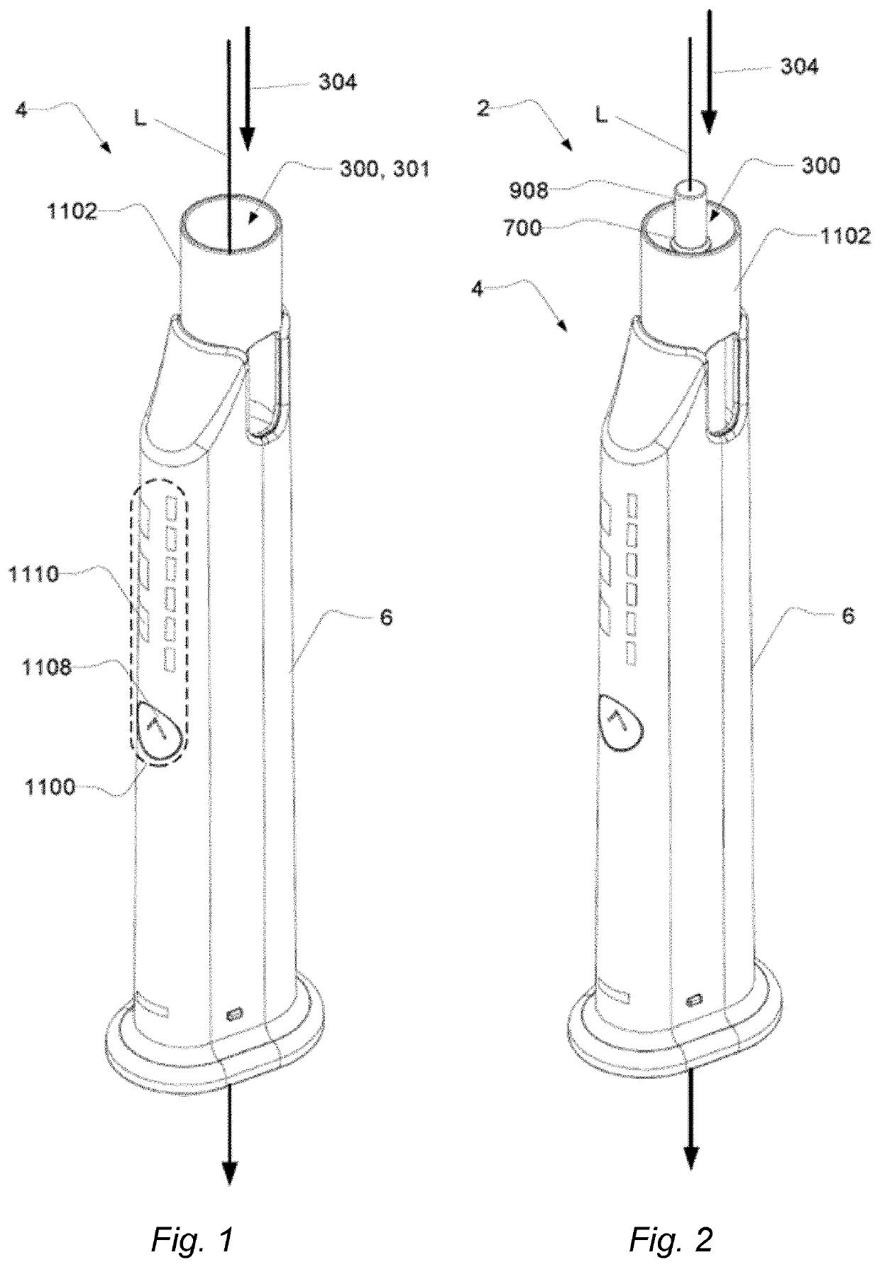
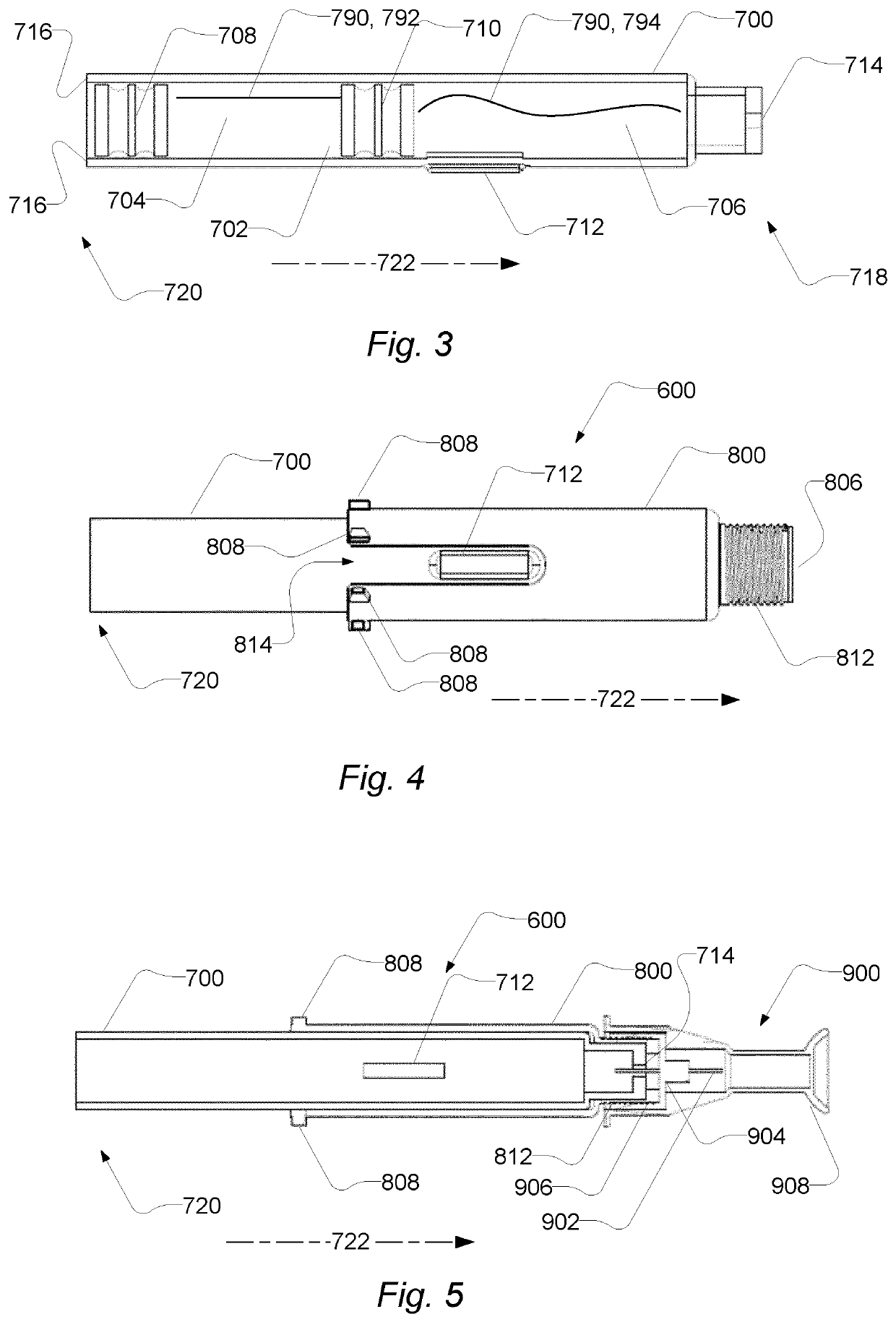
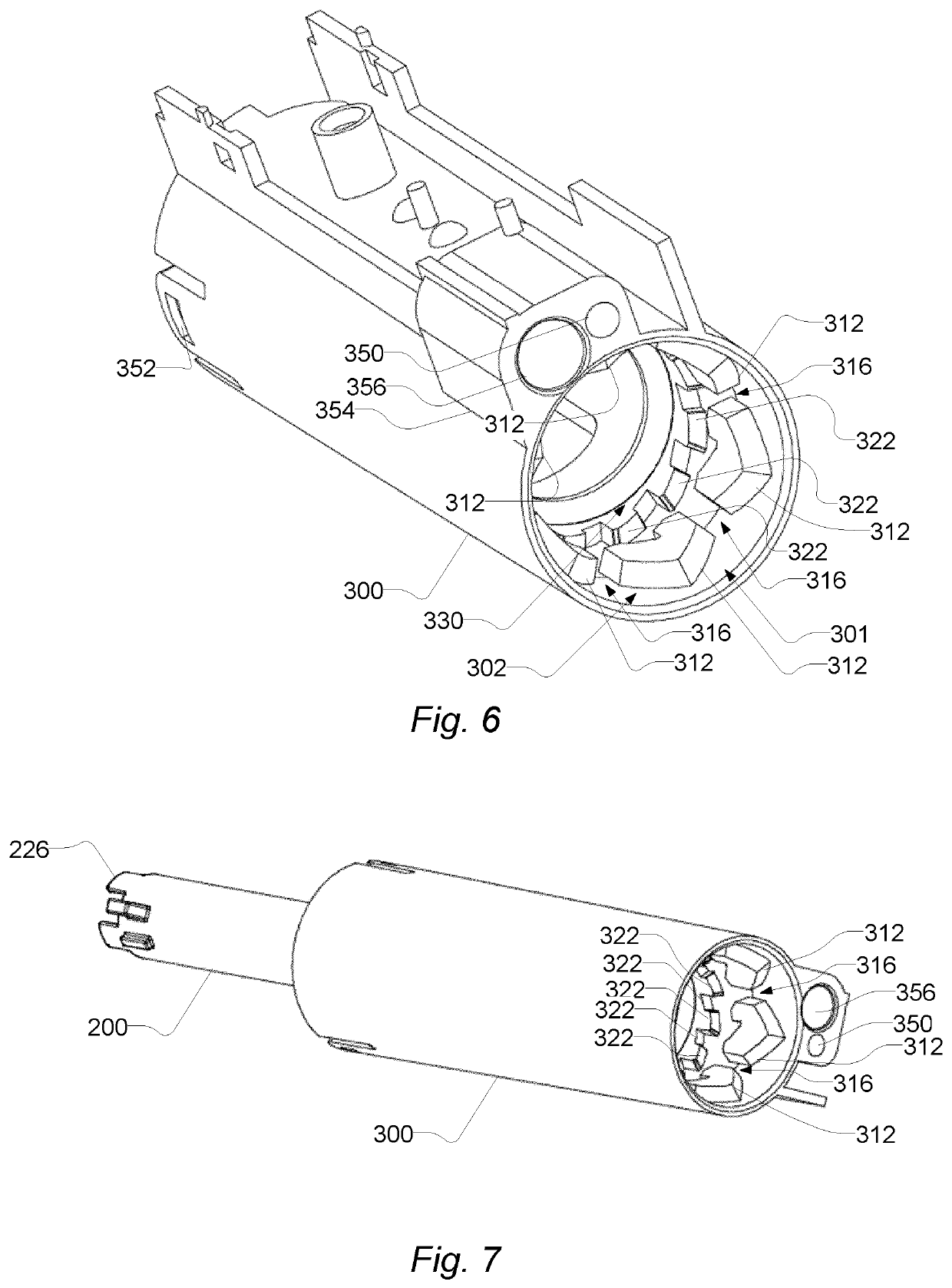
An auto injector (4) for administering injection of a medicament from a cartridge (700) containing the medicament, the auto injector comprising: a cartridge receiver (300) with a cartridge receiver compartment (302) configured to receive a cartridge assembly (600) with at least one cartridge retention member (808) when inserted through a cartridge receiver opening (302) along a longitudinal axis; and an ejector (200) configured to support the cartridge assembly (600) by being suspended to move along the longitudinal direction and being spring-loaded in the direction opposite of the receiving direction. The cartridge receiver compartment (302) has a first section (310), at a first distance from the cartridge receiver opening (301), with inwardly extending first guide members (312) that extends over first guide member angles (314) and are spaced apart to form a passage (316) at passage angles (318) between the inward first guide members (312); wherein the inward first guide members (312) form a first bore (320) accepting the cartridge assembly (600) when inserted through the cartridge receiver opening (301). The cartridge receiver compartment (302) has a second section (330) with an annular shape, at a second distance from the cartridge receiver opening (301), and with second guide members (322) with first faces (324) that are inclined about a radial axis to the longitudinal axis and angularly arranged to extend at least partly over the passage angles (318) and the first guide member angles (314).

Description

CROSS REFERENCE TO RELATED APPLICATIONS[0001]This application is a U.S. National Phase Application of PCT International Application Number PCT / EP2016 / 082856, filed on Dec. 29, 2016, designating the United States of America and published in the English language, which is an International Application of and claims the benefit of priority to European Patent Application No. 15203132.4, filed on Dec. 30, 2015, and European Patent Application No. 15203137.3, filed on Dec. 30, 2015. The disclosures of the above-referenced applications are hereby expressly incorporated by reference in their entireties.[0002]The present invention generally relates to an auto-injector, which is an automatic or semi-automatic drug delivery device adapted to receive a drug filled cartridge and expel a dose therefrom.[0003]In the disclosure of the present invention reference is mostly made to the treatment of Human Growth Hormone, HGH, however, this is only an exemplary use of the auto-injector.[0004]The most co...

Claims


Application Information

Patent Timeline
Patent Type & Authority Patents(United States)
IPC IPC(8): A61M5/24A61M5/20
CPCA61M5/24A61M5/20A61M5/2448A61M5/2033A61M5/2066A61M2005/2433A61M2005/2481A61M2005/2026A61M2005/2485A61M2005/2411A61M5/31585
Inventor FABRICIUS, PAUL ERIKMADSEN, FLEMMINGOLESEN, JAN
Owner ASCENDIS PHARM AS
Learn More