
Lacrimal duct tube

a lacrimal duct and tube technology, applied in the field of lacrimal duct tubes, can solve the problems of poor therapeutic outcomes, heavy patient burden, and damage to the wall of the lacrimal duct sheath, and achieve the effect of convenient checking, simple and safe operation, and smooth movement of the lacrimal duct tub

Active Publication Date: 2020-11-10
KANEKA CORP
View PDF29 Cites 0 Cited by
  • Summary
  • Abstract
  • Description
  • Claims
  • Application Information

AI Technical Summary

Benefits of technology

The design enhances safety and ease of use by preventing the tube from getting caught in the duct wall and allowing smooth movement of the endoscope, enabling simpler and safer rupture into the obstructed site without the need for a sheath, while the colored markings aid in precise placement under endoscopic guidance.

Problems solved by technology

If the operator does not have a high level of operating skill, the bougies may break through the tube or make a hole at a site other than in the normal lacrimal duct (creating a false passage), which results in poor therapeutic outcomes.
According to the SEP technique, however, the lacrimal endoscope is pushed into the sheath and is used to perform complicated procedures such as moving the probe of the lacrimal endoscope covered with the sheath forward and backward like a trombone.
When the sheath is removed from the nose during treatment of the SGI technique, the “ear” gets caught on the wall of the lacrimal duct, and the sheath may damage the wall of the lacrimal duct due to high stiffness of the sheath.
In addition, according to the SGI technique, it is very difficult to grasp and pull out the tip of the sheath coming from the obstructed site under observation by the nasal endoscope, which may cause a heavier burden on the patient.
However, in the case of using the lacrimal duct treatment tool in the insertion surgery similar to SEP, the lacrimal duct treatment tool is long and is likely to be difficult to operate in general.
As described above, the lacrimal duct tubes for the insertion surgery with a combination of SEP and SGI or the insertion surgery similar to SEP that are currently employed in the treatment of lacrimal duct obstruction cannot be said to be sufficient in safely performing the procedures in a simple and easy manner, and the conventional lacrimal duct tube have room for improvement.

Method used

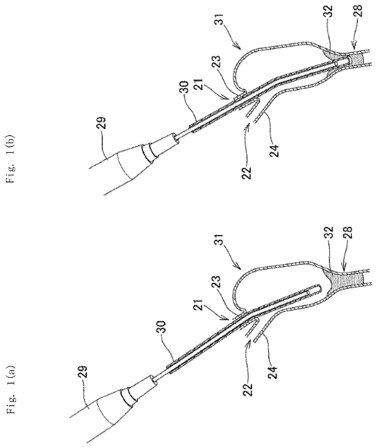
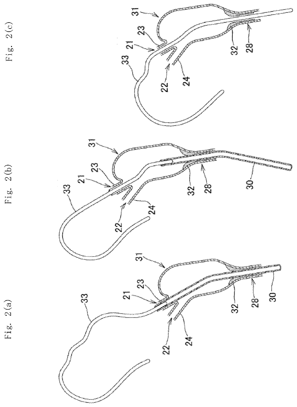
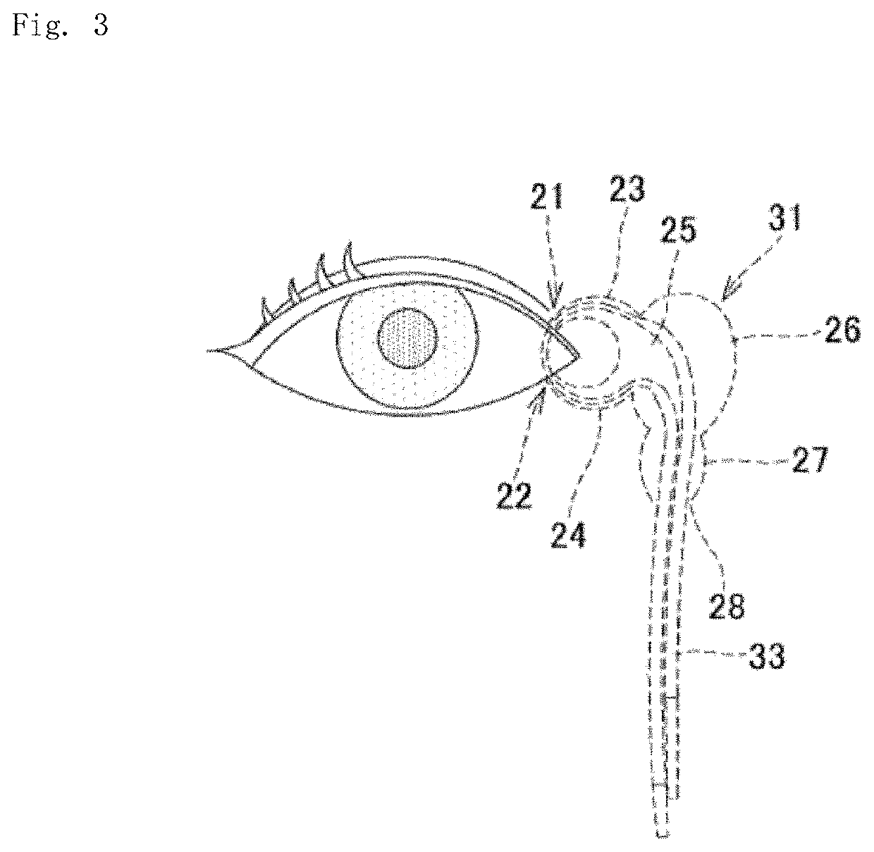

Image

  • Lacrimal duct tube
  • Lacrimal duct tube
  • Lacrimal duct tube

Examples


example 1

[0204]A lacrimal duct tube having the tubular members 2 of the structure illustrated in FIG. 11 was fabricated in such a manner as described below.

[0205]First, a polyurethane tube for base end part of the same diameter was abutted with the other end of a tube in which the terminal end part had a single layer and the main body had a four-layer structure, and a tube for reinforcement member was laid on the surfaces of the tube for main body of the four-layer structure and the tube for base end part including the abutted portions. The side surface of a rod for connection member was connected to the side surface of the tube for reinforcement member, the position of the leading end of the rod was adjusted to come closer to the one end side than the abutted surfaces, and then the connection portions of the tubes were thermally welded.

[0206]Then, the base end part was obliquely cut from a portion near the one end to a portion near the other end to form the inlet / outlet port, thereby fabric...

example 2

[0232]The lacrimal duct tube having a narrow terminal end part was fabricated in such a manner like the example 1 as described above. The narrow terminal end was positioned at the opening side. After the lacrimal duct tube of the example 1 is fabricated, a mandrel in the shape of a rod having a 0.7 mm outer diameter was pushed into the terminal end part of the tubular member from the opening. After that, the tip of the tubular members were thermally compressed using a shrink tube to form a narrow terminal end part (0.5 mm long) with a 0.7 mm inner diameter.

The components of the used members are as follows:

(Tubular Members)

(1) Terminal End Part

[0233]Low-density polyethylene

[0234]Length of the terminal end part: about 4 mm, tapered down with a diameter of 0.9 to 1.3 mm.

In the terminal end part, a lumen has the inside diameter part that got narrow to 0.7 mm in diameter in the section of 0.5 mm in length from the opening at extreme tip end.

(2) Main Body

[0235]Innermost layer: low-density...

example 3

[0243]The lacrimal duct tube 1b having the tubular members 2a of the structure illustrated in FIG. 19 was fabricated in such a manner as described below.

[0244]First, a polyurethane tube for base end part of the same diameter was abutted with the other end of a tube in which the terminal end part 8 had a single layer and the main body 9 had a four-layer structure, and a tube for reinforcement member was laid on the surfaces of the tube for main body of the four-layer structure and the tube for base end part including the abutted portions. The side surface of a rod for connection member was connected to the side surface of the tube for reinforcement member, and the position of the leading end of the rod was adjusted to come closer to the one end side than the abutted surfaces, and then the connection portions of the tubes were thermally welded. Accordingly, the leading end of the connection member 3 was arranged at the same position as the one end side of the tube for reinforcement me...


PUM


Abstract

A lacrimal duct tube includes: a pair of tubular members that each have at one end an opening communicating with a lumen; and a connection member that connects the other ends of the tubular members. A base end part including the other end of at least one of the tubular members is tapered down toward the connection member and the base end part has an inlet / outlet port communicating with the lumen of the tubular member. A portion of the base end part constituting peripheral edge of the inlet / outlet port and the connection member are connected together.

Description

CROSS REFERENCE TO RELATED APPLICATIONS[0001]This application is a Continuation-in-Part of PCT International Application No. PCT / JP2015 / 051274, filed on Jan. 19, 2015, which claims priority under 35 U.S.C. 119(a) to Patent Application No. 2014-009688, filed in Japan on Jan. 22, 2014, all of which are hereby expressly incorporated by reference into the present application.TECHNICAL FIELD[0002]The present invention relates to a lacrimal duct tube for use in treatment of lacrimal duct obstruction.BACKGROUND ART[0003]Treatment methods for lacrimal duct obstruction resulting in epiphora include: (i) probing by a lacrimal duct bougie, (ii) placement of a lacrimal duct tube; (iii) dacryocystorhinostomy (DCR); (iv) lacrimal canaliculization; (v) nasolacrimal duct plastic surgery; (vi) lacrimal caruncle moving surgery, and the like.[0004]The probing by a lacrimal duct bougie in (i) is intended to insert a narrow tube called bougie into a lacrimal duct to open an obstructed site and reconstru...

Claims


Application Information

Patent Timeline
Patent Type & Authority Patents(United States)
IPC IPC(8): A61F9/007A61M27/00
CPCA61F9/00772A61M27/002A61M2210/0612
Inventor KOGA, CHIHIROOGINO, EIJIHIRAI, FUMIYASUFUKAYA, KOHEIMIYAUCHI, HIDEKAZUMATSUMOTO, MARIKO
Owner KANEKA CORP
Learn More