
Connecting structure for steel tube truss and tower barrel of lattice wind power generation tower, prestressed polygon wind tower provided with circular box girder for direct fan on top of tower, wind power generation tower, and wind tower having prestressed anti-fatigue structure

a technology of connecting structure and lattice which is applied in the direction of wind power generation tower, building type, construction, etc., can solve the problems of poor ability to withstand stress at the connection position, waste of manufacturing materials, and difficult point in the design of lattice wind tower, so as to simplify the connection mode and simplify the manufacturing and installation steps. , the effect of saving materials

Active Publication Date: 2020-11-03
QINGDAO HUA STRONG ENERGY TECH CO LTD
View PDF25 Cites 1 Cited by
  • Summary
  • Abstract
  • Description
  • Claims
  • Application Information

AI Technical Summary

Benefits of technology

The patent text describes several new wind power generation tower structures that improve on existing designs. These structures include a connecting structure between the steel tube truss and tower barrel of a lattice wind power generation tower that simplifies the connection between these components, reduces stress, and saves material. Other features include a prestressed polygon wind tower with a direct-fan circular box girder on the top, which simplifies the connection between the tower body and engine room, reduces material usage, and increases production efficiency. Additionally, the new tower structures can adapt to the running space requirement of the blade, simplify manufacturing and installation steps, reduce costs, and increase production efficiency. Overall, these new structures enhance utilization rate of materials, prolong fatigue life, and are convenient to construct.

Problems solved by technology

For the lattice wind power generation tower frame, the transition section connecting the lattice steel tube truss and the fan tower barrel is an important structure, which suffers from large action force and has concentrated force positions, therefore, in the design of the lattice wind tower, the connecting transition of the steel tube truss to the fan tower barrel is a difficult point in the design of the lattice wind tower.
The inventors found in the research that the connecting transition of the conventional steel tube truss to the fan tower barrel has at least the following disadvantages: 1. the connection mode and the connection relationship are complicated, resulting in waste of the manufacturing materials; and 2. the ability to withstand stress at the connection position is poor, causing that breakage accidents easily occur.

Method used


Image

  • Connecting structure for steel tube truss and tower barrel of lattice wind power generation tower, prestressed polygon wind tower provided with circular box girder for direct fan on top of tower, wind power generation tower, and wind tower having prestressed anti-fatigue structure
  • Connecting structure for steel tube truss and tower barrel of lattice wind power generation tower, prestressed polygon wind tower provided with circular box girder for direct fan on top of tower, wind power generation tower, and wind tower having prestressed anti-fatigue structure
  • Connecting structure for steel tube truss and tower barrel of lattice wind power generation tower, prestressed polygon wind tower provided with circular box girder for direct fan on top of tower, wind power generation tower, and wind tower having prestressed anti-fatigue structure

Examples


embodiment 1

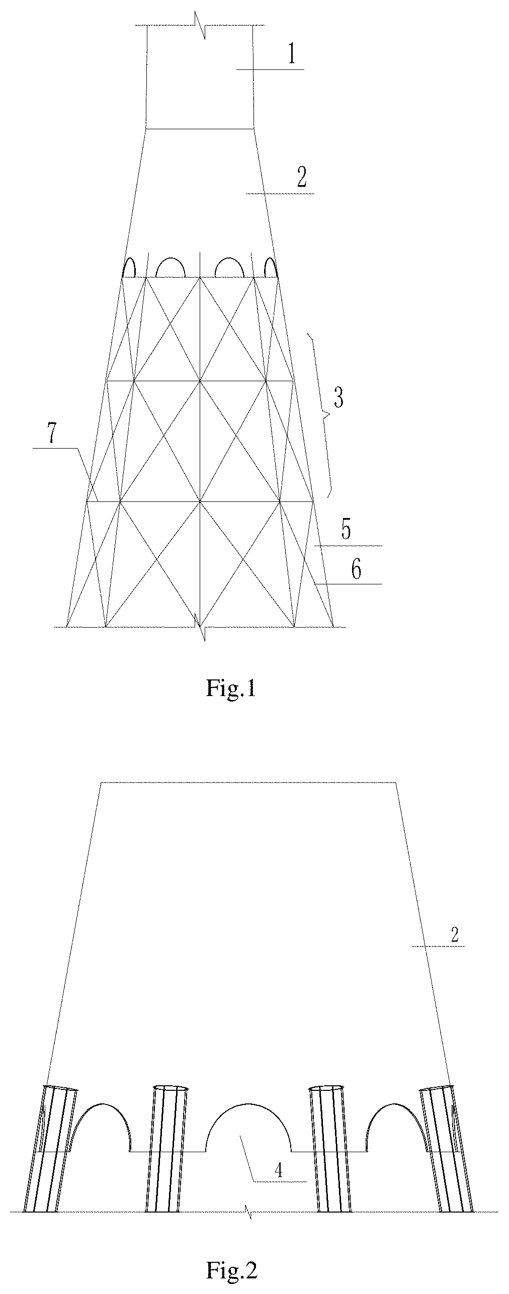
[0057]The wind power generation tower as shown in FIG. 1 comprises a steel-structure lattice tower body 3 with a cross section in a shape of n-regular polygon, a tower barrel 1 and a transition section 2. The lattice tower body 3 is a steel tube truss constituted by n steel tube tower pillars 5, cross bars 7 and diagonal bars 6, with the steel tube truss connected to the tower barrel 1 by the transition section 2. FIG. 2 shows the connection part between the transition section 2 and the steel tube tower pillars 5. A U-type groove 10 (as shown in FIG. 4) is provided at the upper end portion of the steel tube tower pillar 5, and the barrel wall 11 of the transition section is inserted into the U-shaped groove 10. As shown in FIG. 3, the steel tube tower pillar 5 is connected with the barrel wall 11 of the transition section by a butt weld 9, with a pore 8 remaining at the end portion of the U-type groove 10. The transition section 2 is provided with a semi-circular groove 4 between ev...

embodiment 2

[0062]The present embodiment is a prestressed polygon wind tower provided with a direct-fan circular box girder on the top of the tower, having all the characteristics of the connecting structure of the steel tube truss and the tower barrel of the lattice wind power generation tower. The connecting structure having the steel tube truss and the tower barrel of the lattice wind power generation tower described in Embodiment 1 is also applicable to the present embodiment, and the technical solutions already disclosed in Embodiment 1 are not repeatedly described.

[0063]Specifically, the difference between the present embodiment and Embodiment 1 is that the present embodiment is a prestressed polygon wind tower provided with a direct-fan circular box girder on the top of the tower. Referring to FIG. 5-FIG. 10, the prestressed polygon wind tower provided with a direct-fan circular box girder on the top of the tower in the present embodiment, as shown in FIG. 5, comprises a steel-structure ...

embodiment 3

[0069]The present embodiment is a wind power generation tower having all the characteristics of the connecting structure of the steel tube truss and the tower barrel of the lattice wind power generation tower. The connecting structure having the steel tube truss and the tower barrel of the lattice wind power generation tower described in Embodiment 1 is also applicable to the present embodiment, and the technical solutions already disclosed in Embodiment 1 are not repeatedly described.

[0070]Specifically, the difference between the present embodiment and Embodiment 1 is that the present embodiment is a wind power generation tower. Referring to FIG. 11-FIG. 15, a wind power generation tower of the present embodiment, as shown in FIG. 11, comprises a tower frame (similar to the tower pillar 14) and a tower barrel 26 (similar to the tower barrel 1) disposed above the tower frame (similar to the tower pillar 14), wherein the tower frame (similar to the tower pillar 14) and the tower barr...


PUM


Abstract

A connecting structure for a steel tube truss and a tower barrel of a lattice wind power generation tower, a prestressed polygon wind tower provided with a circular box girder for a direct fan on the top of the tower, a wind power generation tower, and a wind tower having a prestressed anti-fatigue structure, which relate to the technical field of wind power generation towers, can simplify the connection mode between the tower barrel and the lattice tower frame, resolve the stress problem, enable the force transmission of a transition section to be direct and save materials.

Description

TECHNICAL FIELD[0001]The present disclosure relates to the technical field of wind power generation towers, to be more specific, relates to a connecting structure for a steel tube truss and a tower barrel of a lattice wind power generation tower, a prestressed polygon wind tower provided with a direct-fan circular box girder on the top of the tower, a wind power generation tower, and a wind tower having a prestressed anti-fatigue structure.BACKGROUND OF THE INVENTION[0002]Wind power generation technology, which requires fuel and a small occupied area and is clean and environmentally friendly, has increasingly become a key development field of the country. As a generator support member, the wind power generation tower frame needs to be light and stable, which can ensure a strong carrying capacity and take into account economic costs.[0003]For the lattice wind power generation tower frame, the transition section connecting the lattice steel tube truss and the fan tower barrel is an im...

Claims


Application Information

Patent Timeline
Patent Type & Authority Patents(United States)
IPC IPC(8): E04H12/10F03D13/20E04H12/16
CPCE04H12/16F03D13/20E04H12/10F05B2240/9121Y02E10/728Y02E10/72
Inventor WANG, TONGHUALV, ZHAOHUA
Owner QINGDAO HUA STRONG ENERGY TECH CO LTD
Learn More