Six lens optical image capturing system having visible and infrared image planes

an optical image and image plane technology, applied in the field can solve the problems of conventional optical systems which cannot provide higher optical performance, and achieve the effects of reducing the height of the optical system, enhancing the capability of aberration correction, and improving the accuracy of optical image capture systems

Active Publication Date: 2020-10-27
ABILITY OPTO ELECTRONICS TECH
View PDF15 Cites 6 Cited by
  • Summary
  • Abstract
  • Description
  • Claims
  • Application Information

AI Technical Summary

Benefits of technology

[0006]The aspect of embodiment of the present disclosure directs to an optical image capturing system and an optical image capturing lens which uses a combination of refractive powers, convex and concave surfaces of six lenses (the convex surface or concave surface in the present invention is the change of geometrical shape of the object side or an image side of each lens at different heights from an optical axis) to increase the amount of light admitted into the optical image capturing system, and to elevate quality of image formation, so that the optical image capturing system can be applied to the minimized electronic products.
[0007]Furthermore, in certain application of optical imaging, there will be a need to capture an image underway for recording or analyzing the light of the visible wavelength and the infrared wavelength, for example, an IP video surveillance camera. IP video surveillance camera may need to be equipped with a Day & Night function. The main reason is that the visible spectrum for human vision has wavelengths ranging from 400 to 700 nm, but the image formed on the camera sensor includes infrared light, which is invisible to human eyes. Therefore, based on the circumstances, an IR cut filter removable (ICR) is placed in front of the camera lens of the IP video surveillance camera in order to increase the “fidelity” of the image, which can prevent infrared light and color shift in the daytime; which can also allow infrared light coming at night to elevate luminance. Nevertheless, the elements of the ICR occupy a significant amount of space and are expensive, which impedes the design and manufacture of miniaturized surveillance cameras in the future.
[0008]One aspect of embodiment of the present invention directs to an optical image capturing system and an optical image capturing camera lens simultaneously. The optical image capturing system and an optical image capturing camera lens can utilize the combination of refractive powers, convex surfaces and concave surfaces of four lens and the selection of materials thereof to reduce the difference between the imaging focal length of visible light and imaging focal length of infrared light and to achieve the near “confocal” effect without the use of an ICR element.

Problems solved by technology

A conventional optical system which cannot provide higher optical performance is required.
Therefore, it is an important issue about how to effectively increase the amount of light admitted into the optical image capturing system and further elevate the image quality thereof.

Method used


Image

  • Six lens optical image capturing system having visible and infrared image planes
  • Six lens optical image capturing system having visible and infrared image planes
  • Six lens optical image capturing system having visible and infrared image planes

Examples


first embodiment

The First Embodiment

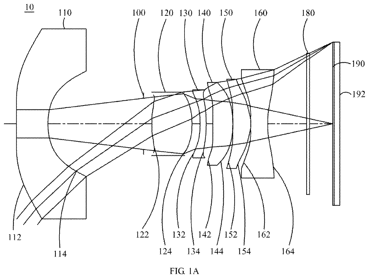
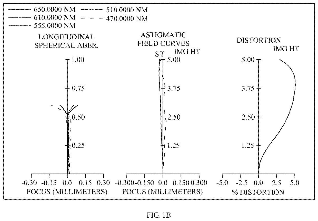
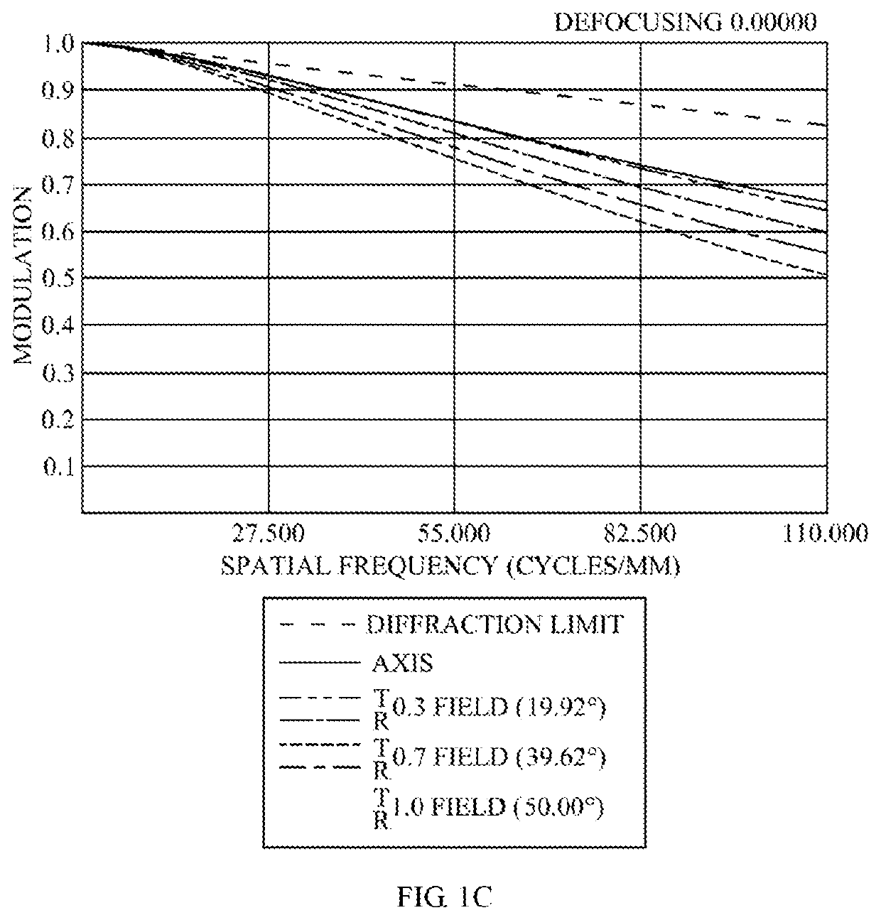
[0116]Please refer to FIG. 1A and FIG. 1B, wherein FIG. 1A is a schematic view of the optical image capturing system according to the first embodiment of the present invention and FIG. 1B shows the longitudinal spherical aberration curves, astigmatic field curves, and optical distortion curve of the optical image capturing system in the order from left to right according to the first embodiment of the present invention. FIG. 1C is a characteristic diagram of modulation transfer of a visible light according to the first embodiment of the present invention. FIG. 1D is a diagram showing the through focus MTF values (Through Focus MTF) of visible light spectrum at the central field of view, 0.3 field of view, and 0.7 field of view of the first embodiment of the present invention. FIG. 1E is a diagram showing the through focus MTF values of infrared light spectrum at the central field of view, 0.3 field of view, and 0.7 field of view of the first embodiment of the pre...

second embodiment

[0189]Please refer to FIG. 2A and FIG. 2B. FIG. 2A is a schematic view of the optical image capturing system according to the second embodiment of the present invention. FIG. 2B shows the longitudinal spherical aberration curves, astigmatic field curves, and optical distortion curve of the optical image capturing system of the second embodiment, in the order from left to right. FIG. 2C is a characteristic diagram of modulation transfer of a visible light according to the second embodiment of the present invention. FIG. 2D is a diagram showing the through focus MTF values (Through Focus MTF) of visible light spectrum at the central field of view, 0.3 field of view, and 0.7 field of view of the second embodiment of the present invention. FIG. 2E is a diagram showing the through focus MTF values of infrared light spectrum at the central field of view, 0.3 field of view, and 0.7 field of view of the second embodiment of the present invention. As shown in FIG. 2A, in the order from the o...

third embodiment

[0205]Please refer to FIG. 3A and FIG. 3B. FIG. 3A is a schematic view of the optical image capturing system according to the third embodiment of the present invention. FIG. 3B shows the longitudinal spherical aberration curves, astigmatic field curves, and optical distortion curve of the optical image capturing system, in the order from left to right, according to the third embodiment of the present invention. FIG. 3C is a characteristic diagram of modulation transfer of a visible light according to the third embodiment of the present invention. FIG. 3D is a diagram showing the through focus MTF values (Through Focus MTF) of visible light spectrum at the central field of view, 0.3 field of view, and 0.7 field of view of the third embodiment of the present invention. FIG. 3E is a diagram showing the through focus MTF values of infrared light spectrum at the central field of view, 0.3 field of view, and 0.7 field of view of the third embodiment of the present invention. As shown in F...


PUM


Abstract

An optical image capturing system is provided. In order from an object side to an image side, the optical image capturing system includes a first lens, a second lens, a third lens, a fourth lens, a fifth lens, and a sixth lens. At least one lens among the first lens to the fifth lens has positive refractive power. The sixth lens may have negative refractive power and an object side and an image side thereof are aspherical wherein at least one surface of the sixth lens has an inflection point. The optical image capturing system has six lenses with refractive power. When meeting some certain conditions, the optical image capturing system may have outstanding light-gathering ability and an adjustment ability about the optical path in order to elevate the image quality.

Description

CROSS-REFERENCE TO RELATED APPLICATION[0001]This application claims priority from Taiwan Patent Application No. 107104562, filed on Feb. 8, 2018, in the Taiwan Intellectual Property Office, the content of which is hereby incorporated by reference in its entirety for all purposes.BACKGROUND OF THE INVENTION1. Field of the Invention[0002]The present disclosure relates to an optical image capturing system, and more particularly is about a minimized optical image capturing system which can be applied to electronic products.2. Description of the Related Art[0003]In recent years, with the rise of portable electronic devices having camera functionalities, the demand for an optical image capturing system has gradually been raised. The image sensing device of the ordinary photographing camera is commonly selected from a charge coupled device (CCD) or a complementary metal-oxide semiconductor sensor (CMOS Sensor). Also, as advanced semiconductor manufacturing technology enables the minimizati...

Claims


Application Information

Patent Timeline
Patent Type & Authority Patents(United States)
IPC IPC(8): G02B9/62G02B13/00G02B27/00G02B9/64G02B13/14
CPCG02B13/0045G02B9/62G02B13/008G02B13/14G02B9/64G02B27/0012G02B13/146G02B1/041
Inventor CHANG, YEONG-MINGLIAO, KUO-YULAI, CHIEN-HSUNLIU, YAO-WEI
Owner ABILITY OPTO ELECTRONICS TECH
Why Eureka
Try Eureka