Image processing device and image processing method
a technology of image processing and image processing, applied in the field of image processing device and image processing method, can solve the problems of difficult to perform further correct diagnosis, inability to discriminate a lesion to be detected, and inability to correctly grasp the shape of a diagnosis object organ, etc., to achieve the effect of improving diagnosis efficiency
- Summary
- Abstract
- Description
- Claims
- Application Information
AI Technical Summary
Benefits of technology
Problems solved by technology
Method used
Image
Examples
first embodiment
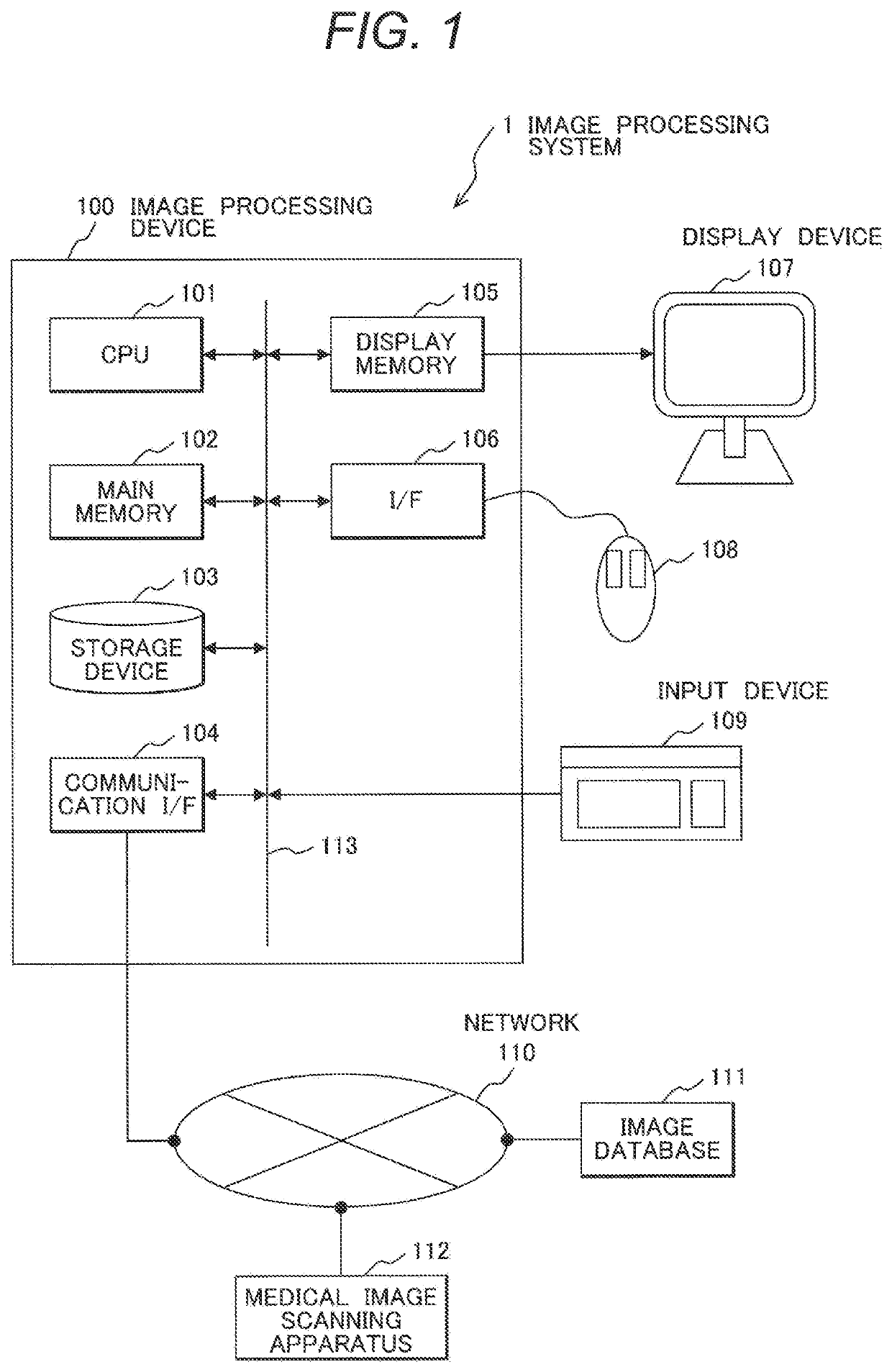
[0033]First, the configuration of an image processing system 1 to which an image processing device 100 according to the present invention is applied will be described with reference to FIG. 1.
[0034]As shown in FIG. 1, the image processing system 1 has the image processing device 100, an image database 111 connected to the image processing device 100 via a network 110, and a medical image scanning apparatus 112.
[0035]The image processing device 100 is a computer to perform processing including image generation and image analysis. As shown in FIG. 1, the image processing device 100 has a CPU (Central Processing Unit) 101, a main memory 102, a storage device 103, a communication interface (communication I / F) 104, a display memory 105, and an interface (I / F) 106 with respect to external devices such as a display device 107, an input device 109, and a mouse 108. The respective elements are connected via a bus 113.
[0036]The CPU 101 reads a program stored in the main memory 102, the storag...
second embodiment
[0088]The partially emphasized image generation processing according to a second embodiment will be described. The image processing device 100 according to the second embodiment offsets the emphasis effect in the not-diagnosed region 31b to generate the partially emphasized image 39. Note that the configuration of the image processing device 100 according to the second embodiment and the flow of entire processing are the same as those in the first embodiment. Hereinbelow, explanations overlapped with those in the first embodiment will be omitted, but the difference will be described. Further, the respective elements identical to those in the image processing device 100 according to the first embodiment will have the same reference numerals in the description.
[0089]As shown in FIG. 15, the CPU 101 first calculates a mean difference value between the diagnostic image 31 and the emphasized image 33 by evaluation block (see FIG. 8). A part where no change occurs before and after the emp...
third embodiment
[0093]As a third embodiment of the present invention, a display example of the emphasis region and an editing operation of the region will be described. Note that the configuration of the image processing device 100 according to the third embodiment and the flow of entire processing are the same as those in the first embodiment. Hereinbelow, the overlapped explanations will be omitted, and the identical respective elements will have the same reference numerals in the description.
[0094]The emphasis region calculated at step S106 is determined based on a parameter previously stored in the storage device 103 of the image processing device 100 or a parameter inputted by the operator. However, the region intended by the operator is not necessarily calculated as the emphasis region. To handle this problem, the image processing device 100 according to the third embodiment provides a user interface for the operator to edit the emphasis region.
[0095]FIG. 17 shows an example of an emphasis re...
PUM
 Abstract
Description
Claims
Application Information
 - R&D
- Intellectual Property
- Life Sciences
- Materials
- Tech Scout
- Unparalleled Data Quality
- Higher Quality Content
- 60% Fewer Hallucinations
Browse by: Latest US Patents, China's latest patents, Technical Efficacy Thesaurus, Application Domain, Technology Topic, Popular Technical Reports.
© 2025 PatSnap. All rights reserved.Legal|Privacy policy|Modern Slavery Act Transparency Statement|Sitemap|About US| Contact US: help@patsnap.com


