Faster fault-detection mechanism, for example using bidirectional forwarding detection (BFD), on network nodes and/or hosts multihomed using a link aggregation group (LAG)

a fault detection and fast technology, applied in the field of communication networks, can solve problems such as service degradation, 3-5 seconds to detect faults along the interface, and connection point to poin

Active Publication Date: 2020-10-13
JUMIPER NETWORKS INC
View PDF9 Cites 5 Cited by
  • Summary
  • Abstract
  • Description
  • Claims
  • Application Information

AI Technical Summary

Benefits of technology

The patent describes a method for testing the integrity of a network using a message sent over multiple communication links. The message includes a destination IP address and a payload containing path testing information. The testing is done by checking the destination IP address and processing the information based on the result. The technical effect of this method is to provide a reliable way to test the integrity of a network and detect any potential problem areas in a timely manner.

Problems solved by technology

One problem with standard link aggregation is that the connections are point to point.
Unfortunately, however, even with fastest timeout interval set on LACP, it takes about 3-5 seconds to detect the fault along the interface.
Such a 3-5 second delay can lead to service degradation, which can impact end applications.
(Consequently, the current implementation of BFD is not useful, or at least not specified, for multihomed connections.)
RFC7130 specifies that a destination IP address must be configured on the peer and should be reachable through the LAG interface, but does not provide any clarity on the specifics of destination IP address, thereby permitting different implementations.
These limitations and / or requirements of RFC 7130 shortcomings cause a number of problems.
Second, any change in the IP address would require relevant configuration changes across all participating nodes.
A similar problem occurs for a CE device multihomed (e.g., with a LAG) to PE devices at the edge of a provider transport network.

Method used


Image

  • Faster fault-detection mechanism, for example using bidirectional forwarding detection (BFD), on network nodes and/or hosts multihomed using a link aggregation group (LAG)
  • Faster fault-detection mechanism, for example using bidirectional forwarding detection (BFD), on network nodes and/or hosts multihomed using a link aggregation group (LAG)
  • Faster fault-detection mechanism, for example using bidirectional forwarding detection (BFD), on network nodes and/or hosts multihomed using a link aggregation group (LAG)

Examples


Embodiment Construction

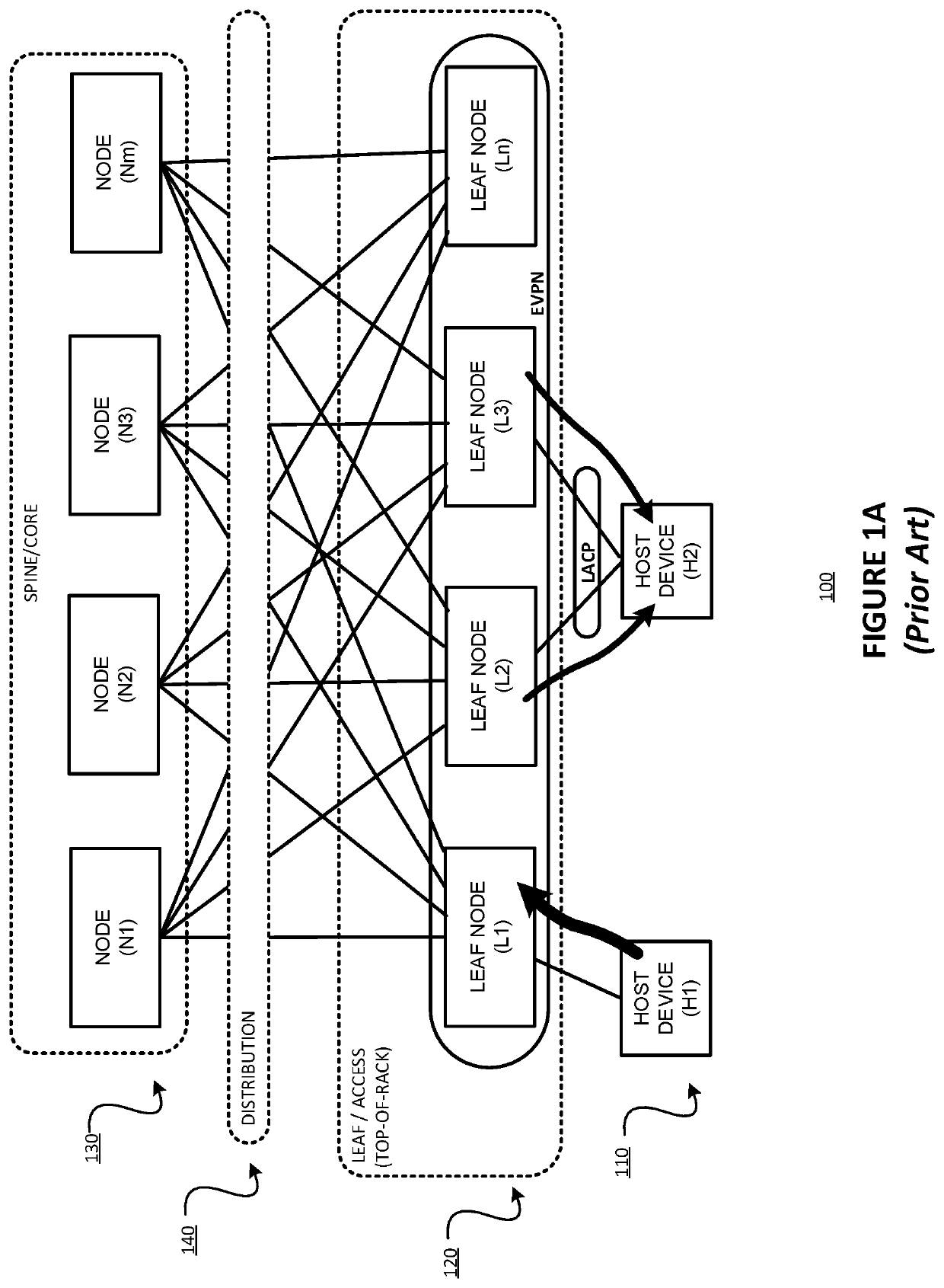
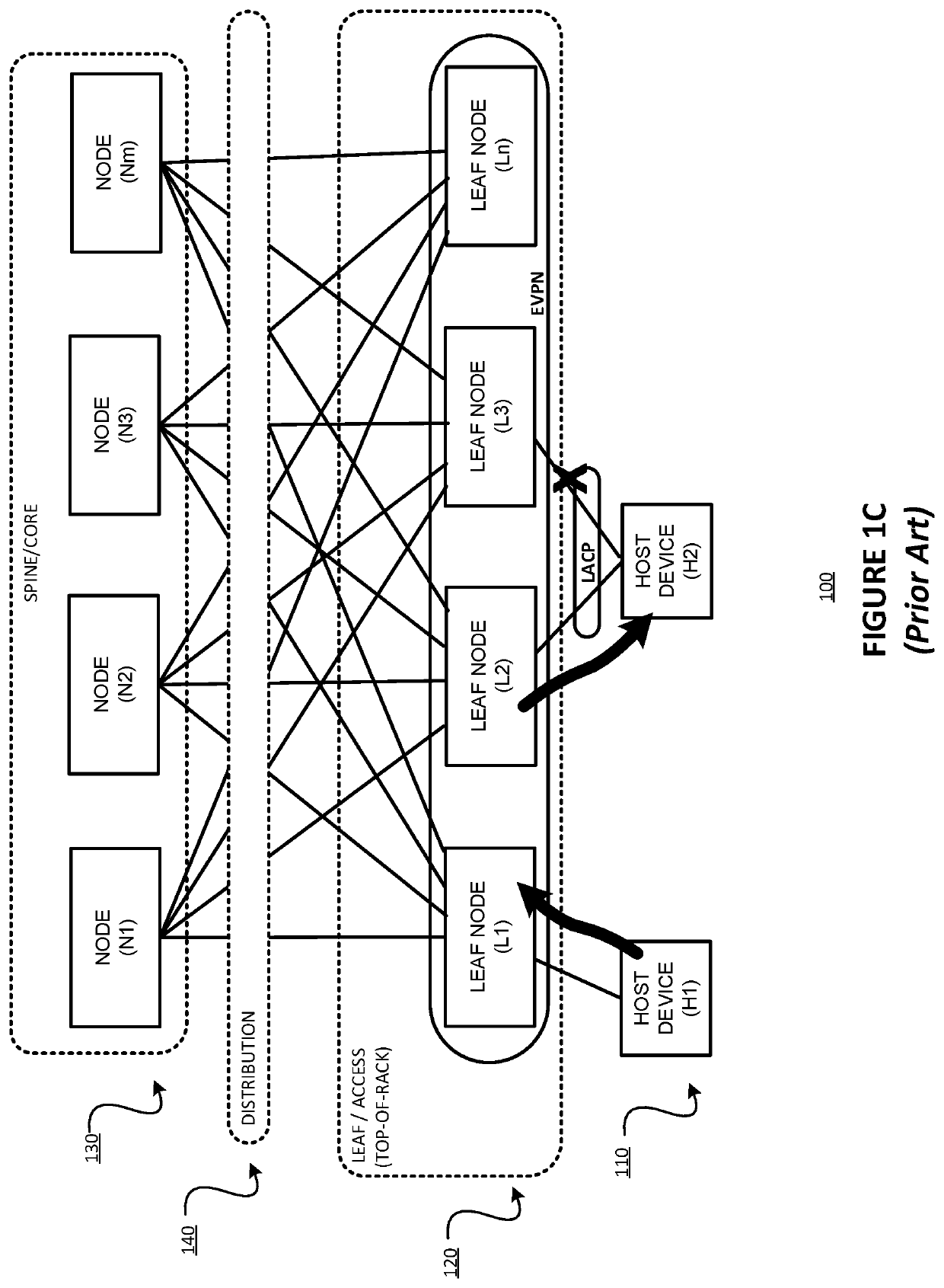
[0050]The present description may involve novel methods, apparatus, message formats, and / or data structures for detecting faults more quickly (e.g., more quickly than 3-5 seconds as in LACP, and preferably with sub-second timing), especially in multihomed environments, and especially in MC-LAGs. The following description is presented to enable one skilled in the art to make and use the invention, and is provided in the context of particular applications and their requirements. Thus, the following description of embodiments consistent with the present invention provides illustration and description, but is not intended to be exhaustive or to limit the present invention to the precise form disclosed. Various modifications to the disclosed embodiments will be apparent to those skilled in the art, and the general principles set forth below may be applied to other embodiments and applications. For example, although a series of acts may be described with reference to a flow diagram, the o...


PUM


Abstract

For use in a system including a first data forwarding device, a second data forwarding device, a third data forwarding device, a first communications link between the first data forwarding device and the second data forwarding device, and a second communications link between the first data forwarding device and the third data forwarding device, the first and second communications links belonging to a link aggregation group (LAG), a method includes (1) generating a message (i) for testing a first path between the first data forwarding device and the second data forwarding device, and a second path between the first data forwarding device and the third data forwarding device, and (ii) including an Internet protocol (IP) datagram including a multicast IP destination address and a payload containing path testing information; and (2) sending, over the LAG, the message from the first data forwarding device to both the second data forwarding device and the third data forwarding device. Responsive to receiving an instance of the message by either of the second or third data forwarding device, such device(s) (1) determine whether or not the received instance of the message is a fault detection on a multihomed link aggregation group message, and (2) processing the received instance of the message based on the determination of whether or not it is a fault detection on a multihomed link aggregation group message.

Description

§ 1. BACKGROUND OF THE INVENTION§ 1.1 Field of the Invention[0001]The present description concerns communications networks. More specifically, the present description concerns detecting faults in communications networks, especially in communications networks having multihomed access, such as via Ethernet Virtual Private Network (EVPN) multihoming for example.§ 1.2 Background Information[0002]§ 1.2.1 Multihoming Examples and Technologies Supporting Multihoming[0003]In an example datacenter environment within the cloud, one design consideration for network architects is that the networks be more resilient and fault tolerant. The desire for resiliency and fault tolerance spans across all or most segments of the cloud-based datacenter; from the host where applications are hosted, to a wide area network (WAN) peering with Internet.[0004]In typical datacenter design, the end host is usually connected to multiple Top of Rack (TOR) nodes (also referred to as “leaf nodes”) using Link-Aggrega...

Claims


Application Information

Patent Timeline
Patent Type & Authority Patents(United States)
IPC IPC(8): H04L12/28H04L12/26H04L45/24H04L45/243H04L45/28
CPCH04L43/50H04L43/0811H04L45/28H04L45/245H04L12/4641H04L12/4633H04L45/22H04L41/06H04L69/14H04L49/555H04L69/40Y02D30/50
Inventor KALBURGI, SURYA PRAKASH S.
Owner JUMIPER NETWORKS INC
Why Eureka
Try Eureka