Method for manufacturing electrical connection assembly

a technology of electrical connection and assembly, which is applied in the direction of soldered/welded connection, other printed circuit details, coupling protective earth/shielding arrangement, etc., can solve the problems of increasing cost, and affecting the reliability of electrical connections

Active Publication Date: 2020-10-13
AUTONETWORKS TECH LTD +2
View PDF14 Cites 0 Cited by
  • Summary
  • Abstract
  • Description
  • Claims
  • Application Information

AI Technical Summary

Benefits of technology

[0008]The method also is directed to a connector suitable for the above-described method. This connector forms an electrical connection assembly by being connected to a wiring material including conductors. The connector has terminals respectively corresponding to the conductors and an insulating housing for collectively holding the terminals in array with the conductors being conductively connectable to the respective terminals while being arranged in an array direction perpendicular to a longitudinal direction of the conductors. Each of the terminals has a conductor connection surface exposed outside the insulating housing from a surface of the insulating housing and is connectable to a part to be connected set in each conductor. The insulating housing includes a housing body having a part for holding the terminals and a fixing portion made of synthetic resin having a lower melting point than a material constituting the housing body. The fixing portion is connected to the housing body to project from a surface of the housing body to be able to contact the wiring material at a fixing position separated in a longitudinal direction of the wiring material from the parts to be connected.

Problems solved by technology

However, in an electrical connection assembly in which conductors on ends of wires are soldered directly to corresponding terminals as described above, tension generated in the wire directly acts on a soldered part and may cause a connection failure.
A connector with a large-scale structure to hinder the action of tension enlarges and complicates the connector and drastically increases cost.

Method used


Image

  • Method for manufacturing electrical connection assembly
  • Method for manufacturing electrical connection assembly
  • Method for manufacturing electrical connection assembly

Examples


Embodiment Construction

[0015]A preferred embodiment of the present invention is described with reference to the drawings.

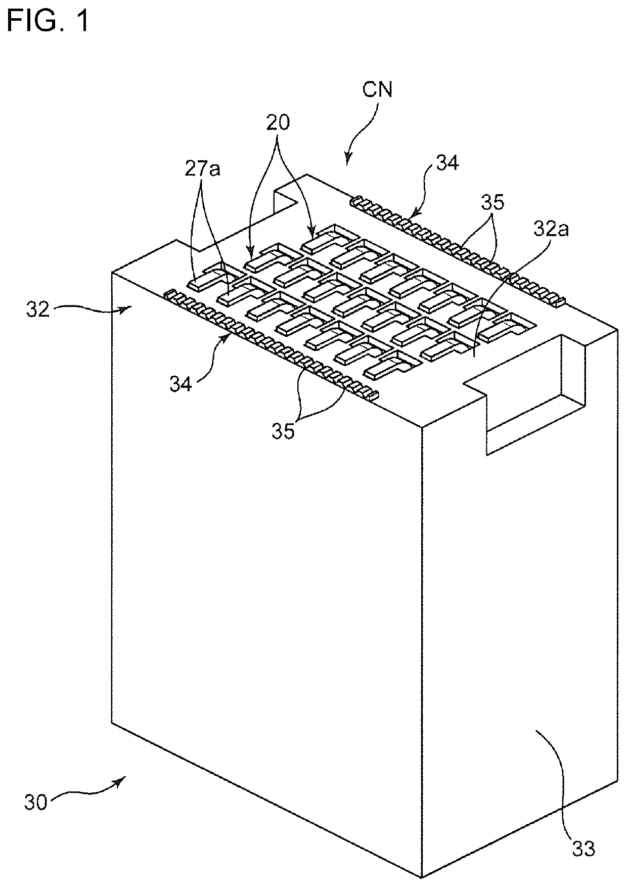
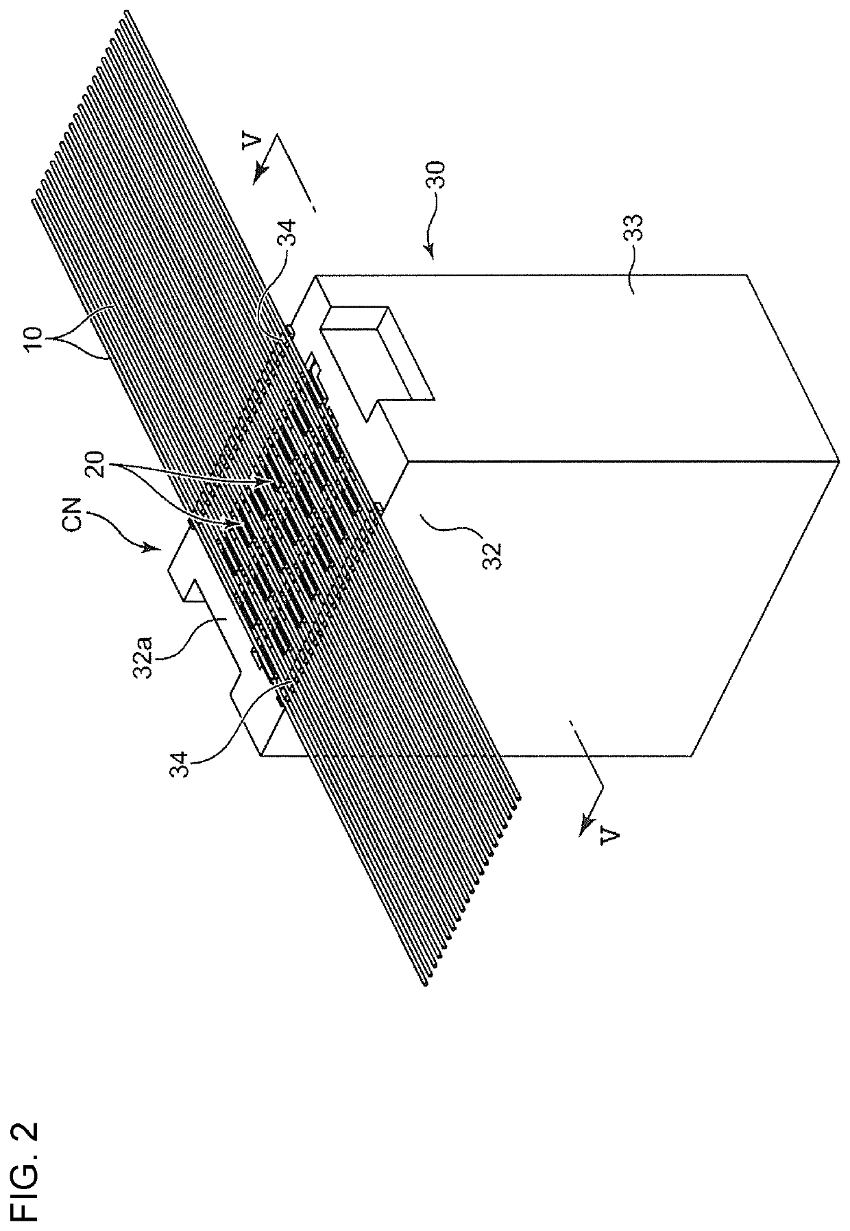
[0016]FIGS. 1 to 6 show a manufacturing method according to this embodiment and an electrical connection assembly manufactured by this method. The electrical connection assembly includes wires 10 constituting a wiring material, and a connector CN for connecting the wires 10 to another connector.

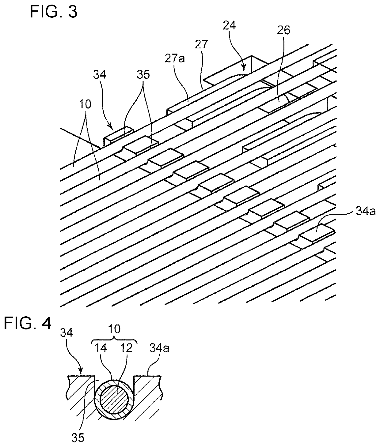
[0017]Each of the wires 10 includes a conductor 12 and an insulation coating 14 for covering the conductor 12, as shown in FIG. 4. The wires 10 are connected to the connector CN while being arranged at intervals parallel to each other in an array direction perpendicular to a longitudinal direction thereof.

[0018]The connector CN includes terminals 20 respectively corresponding to the wires 10 and an insulating housing 30 for collectively holding the terminals 20.

[0019]Each of the terminals 20 according to this embodiment is a male terminal formed of a single long metal plate and includes a held po...


PUM


Abstract

A method is provided for manufacturing an electrical connection assembly includes preparing a connector (CN) in which each terminal (20) has a conductor connection surface (27a) exposed from an insulating housing (30), bringing parts of conductors and the conductor connection surfaces (27a) corresponding thereto into contact and connecting both while tension is applied to a wiring material (10). The method further includes fixing the wiring material (10) to the insulating housing (30) by bringing the wiring material (10) and the insulating housing (30) into contact with each other at the fixing positions separated in the longitudinal direction of the wiring material (10) from the parts to be connected and solidifying the fixing portions (34) of the insulating housing (30) after melting the fixing portions at the fixing positions.

Description

BACKGROUNDField of the Invention[0001]The invention relates to an electrical connection assembly used in an automotive vehicle or the like and including a wiring material and a connector.Related Art[0002]A wiring material used in an automotive vehicle or the like has a flat material in which conductors are arrayed in a direction perpendicular to an axial direction of the conductors. The conductors are connected to terminals in a housing of a connector so that the conductors then can be connected to another circuit.[0003]Conventionally, conductors arrayed as described above are connected directly to the terminals by soldering. This connection of the conductors to the terminals by soldering can simplify the structure of the terminals and make a connecting operation efficient.[0004]Japanese Unexamined Patent Publication No. 2010-146939 discloses a method where wires are prepared to expose conductors by removing insulation coatings at ends of the wires in advance. The prepared wires are...

Claims


Application Information

Patent Timeline
Patent Type & Authority Patents(United States)
IPC IPC(8): H01R4/02H01R13/658H01R43/02H01R43/24H05K1/02H05K3/36H01R43/00
CPCH05K1/02H01R43/02H01R43/0207H05K3/36H01R43/00H01R4/029H01R43/24H01R4/02H01R13/658H05K2201/20H01R4/024H01R4/027H01R43/0228H01R43/0249H01R43/0263
Inventor WASHIO, KAZUHIROHIRAI, HIROKIOMORI, YASUOSHIMIZU, TOSHIO
Owner AUTONETWORKS TECH LTD
Why Eureka
Try Eureka