
Center-of-gravity-of-load position calculator for robot and method thereof

a technology of center-of-gravity and calculator, which is applied in the direction of manipulators, program-controlled manipulators, manufacturing tools, etc., can solve the problem of inability to use such a technique in a horizontal four-axis robot arm which is not capable of changing the position of the workpiece, and achieves fast and simple calculation of the center-of-gravity, enhancing the accuracy of calculating the position, and minimizing mechanical vibration

Active Publication Date: 2020-10-13
DENSO WAVE INC
View PDF3 Cites 3 Cited by
  • Summary
  • Abstract
  • Description
  • Claims
  • Application Information

AI Technical Summary

Benefits of technology

Accurately calculates the position of the center of gravity of a physical load held by a horizontal four-axis robot arm, enhancing accuracy by exerting centrifugal force and minimizing mechanical vibration, and allows for fast and simple calculations by setting specific axis positions.

Problems solved by technology

It is, thus, impossible to use such a technique in a horizontal four-axis robot arm which is not capable of changing the position of the workpiece where the force of gravity acts on the workpiece.

Method used


Image

  • Center-of-gravity-of-load position calculator for robot and method thereof
  • Center-of-gravity-of-load position calculator for robot and method thereof
  • Center-of-gravity-of-load position calculator for robot and method thereof

Examples


Embodiment Construction

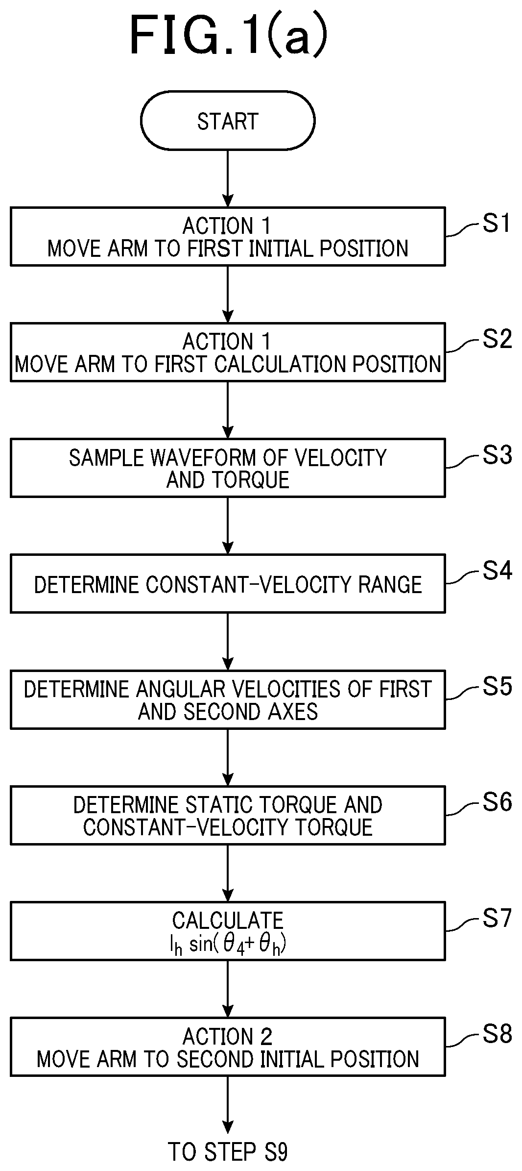
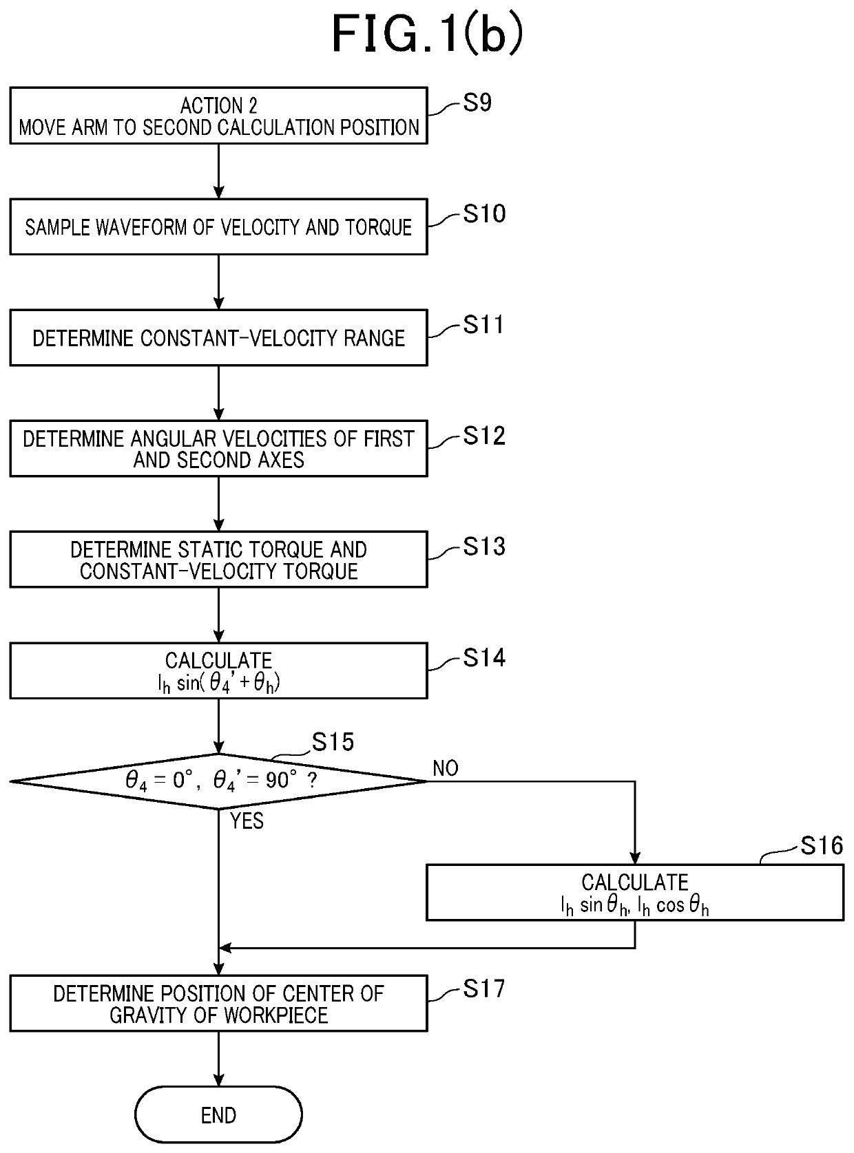
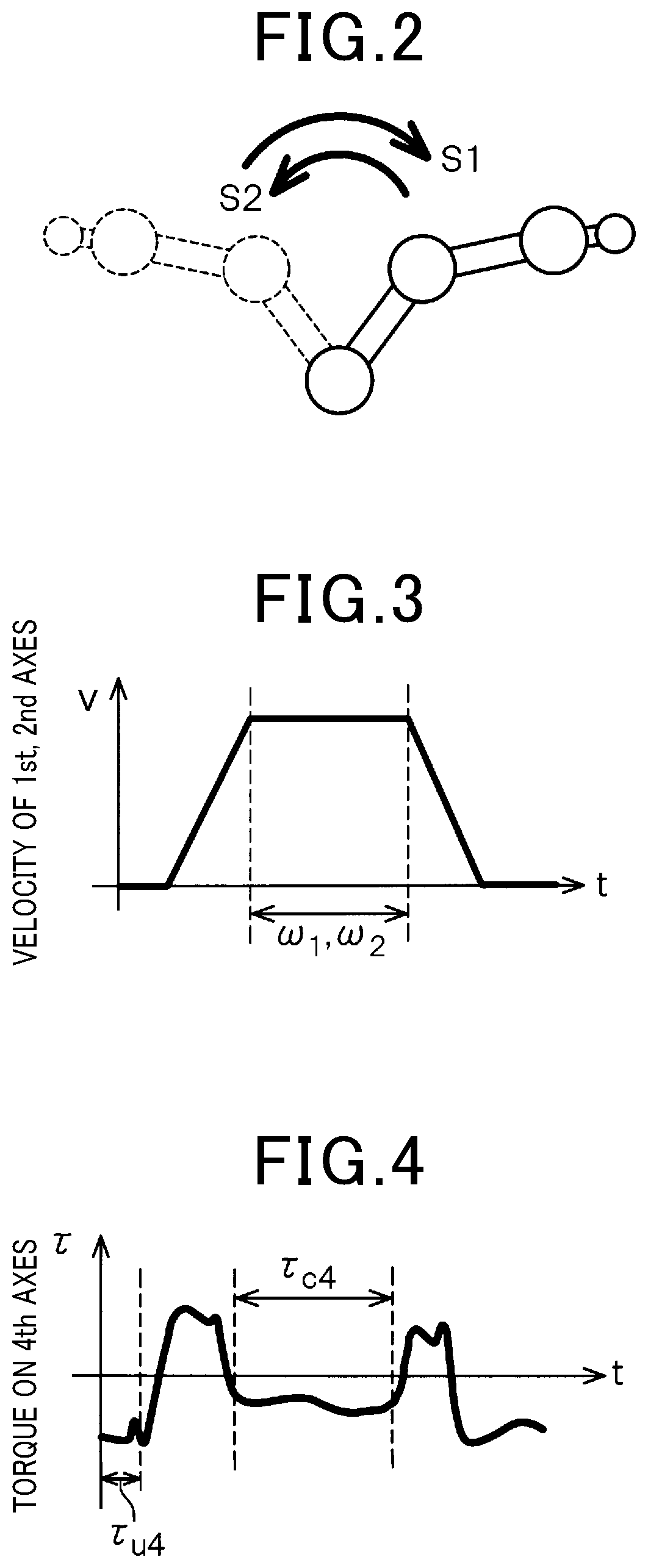
[0034]An embodiment will be described below with reference to the drawings. FIG. 9 illustrates a system structure of a typical industrial robot. Specifically, the robot system 1 includes the robot 2, the controller 3 for controlling an operation of the robot 2, and the teaching pendant 4 connected to the controller 3. The controller 3 works as a control unit and a center-of-gravity-of-load position calculator. The robot 2 is designed as, for example, a four-axis horizontal articulated robot. The robot 2 includes the base 5 secured to a mounting surface, the first arm 6, the second arm 7, and the shaft 8. The first arm 6 is joined to the base 5 to be rotatable around the first axis J1. The first axis J1 is a vertical axis whose longitudinal center line is aligned in a Z-axis direction in a Cartesian coordinate system, as defined below. The second arm 7 is joined to the top end of the first arm 6 to be rotatable around the second axis J2 whose longitudinal center line is aligned in th...


PUM


Abstract

A center-of-gravity-of-load position calculator is provided which determines the position of the center of gravity of a physical load held by a horizontal four-axis robot arm. The center-of-gravity-of-load position calculator moves horizontally move the physical load a plurality of times in conditions where positions of a fourth axis are different from each other and measures degrees of torque acting on the fourth axis during such movement to calculate given first and second parameters. The center-of-gravity-of-load position calculator calculates the position of the center of gravity of the physical load as a function of the first and second parameters. This achieves fast and easy calculation of the position of the center of gravity of the physical load.

Description

CROSS REFERENCE TO RELATED DOCUMENT[0001]The present application claims the benefit of priority of Japanese Patent Application No. 2017-057395 filed on Mar. 23, 2017, the disclosure of which is incorporated herein by reference.BACKGROUND1. Technical Field[0002]The invention relates generally to a center-of-gravity-of-load position calculator which calculates the position of the center of gravity of a physical load held by an end of a horizontal four-axis robot arm and a method thereof.2. Background Art[0003]Japanese Patent No. 5327722 discloses a technique of calculating the position of the center of gravity of a workpiece (i.e., a physical load) held by a vertical six-axis robot arm.[0004]The vertical six-axis robot arm is typically capable of actuating a fifth axis to exert the force of gravity on the workpiece and thus calculating the position of the center of gravity of the workpiece. The technique, as taught in the above publication, is available only for the vertical six-axis ...

Claims


Application Information

Patent Timeline
Patent Type & Authority Patents(United States)
IPC IPC(8): B25J9/16B25J9/00
CPCB25J9/1638B25J9/0048B25J9/1635
Inventor TAKAMURA, NORITAKA
Owner DENSO WAVE INC
Learn More