Mammography system

a technology of mammography and compression pads, which is applied in the field of mammography systems, can solve the problems of difficult to prepare compression pads suitable for all subject sizes, difficult to effectively compress the breast of every man only with one size compression pad, and difficult to perform accurate imaging, so as to improve the convenience of radiologist's imaging manipulation

Active Publication Date: 2020-10-13
VIEWORKS
View PDF18 Cites 0 Cited by
  • Summary
  • Abstract
  • Description
  • Claims
  • Application Information

AI Technical Summary

Benefits of technology

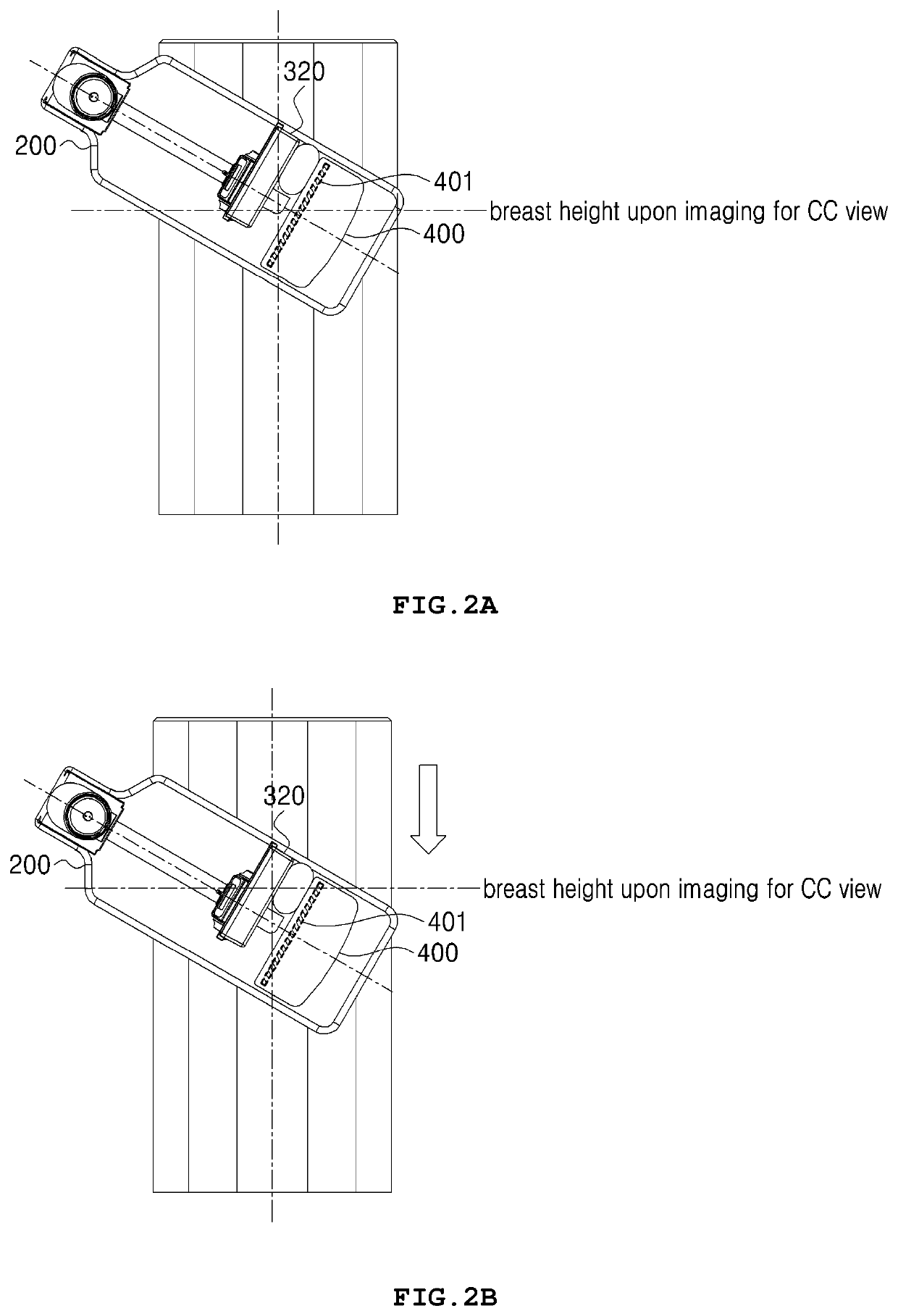
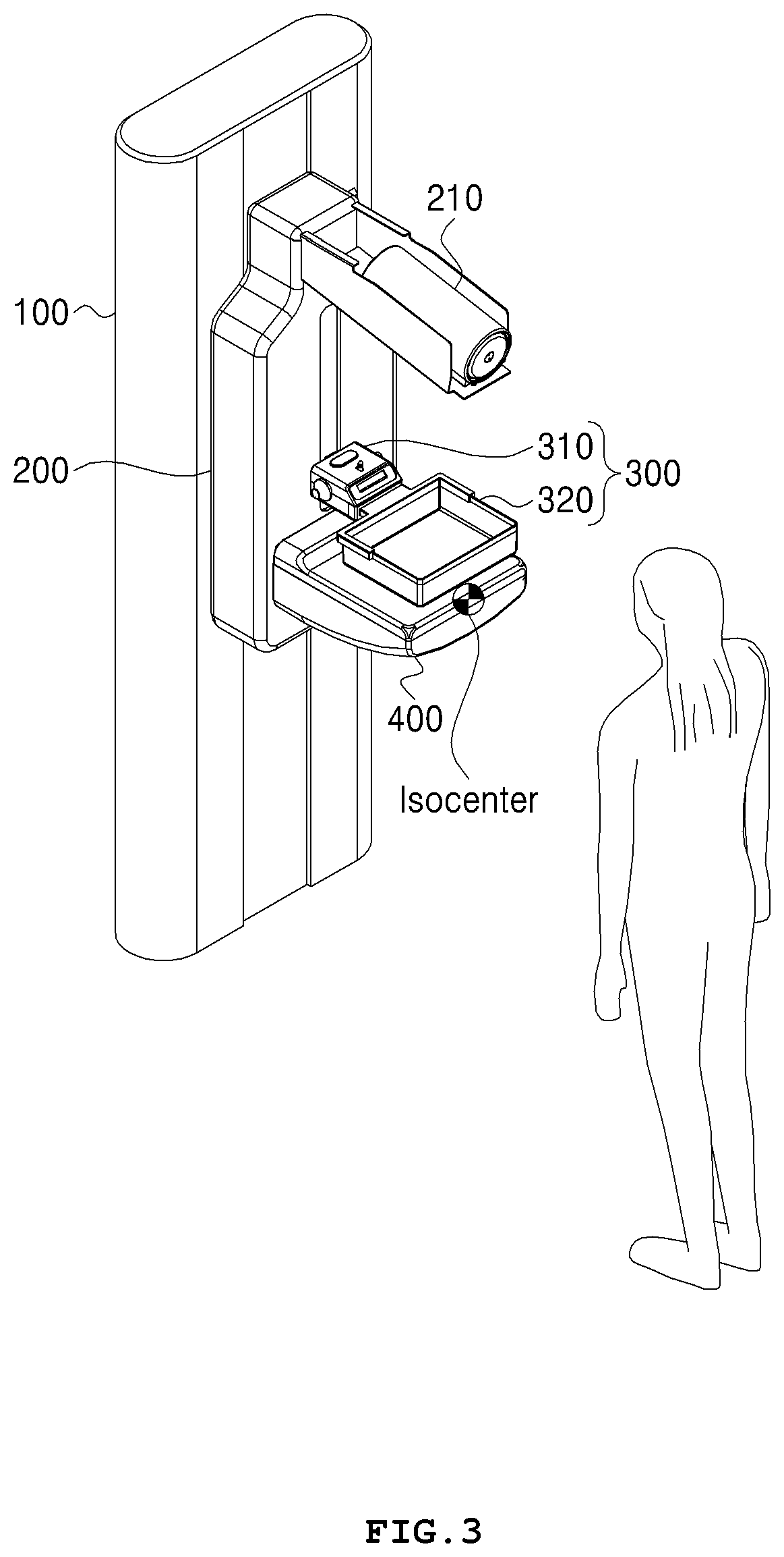
[0007]Accordingly, the present invention has been made in view of the above-mentioned problems occurring in the related art, and it is an object of the present invention to provide a mammography system that is configured, unlike the conventional mammography system, to allow not a compression pad, but an imaging stand to move in left and right directions, thereby improving conveniences in a radiologist's imaging manipulations, and to allow imaging for an MLO view to be carried out through the left and right movements of the imaging stand, without any vertical movement of an arm frame, even though a large x-ray detector is used, thereby optimizing advantages of an isocenter structure (wherein the imaging stand is located at a position corresponding to the isocenter of the arm frame).

Problems solved by technology

Since every man has different breast sizes, however, it is actually hard to effectively compress the breast of every man only with one size compression pad.
However, it is actually hard to prepare the compression pads adequate for all subject sizes, and accordingly, small breasts are often imaged in the state of being compressed by means of large compression pads.
In this case, it is difficult for a radiologist to adjust the position of the subject due to the relatively large compression pad, thereby making it hard to perform accurate imaging, and in conventional practices, accordingly, the compression pad compressing the subject moves in a left or right direction with respect to an arm frame, thereby trying to ensure conveniences in the radiologist's imaging manipulations.
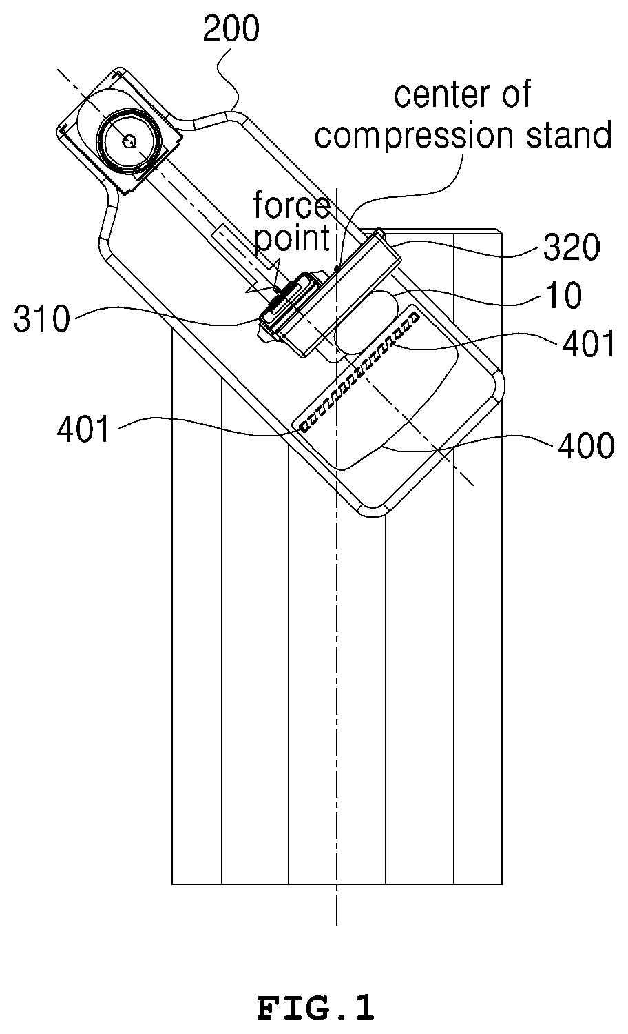
Even in case where the compression pad moves horizontally, however, a force point for applying a compression force to the subject does not correspond to the center of the compression pad to which the compression force is applied, as shown in FIG. 1, so that the compression force applied to the subject cannot be reliable, and above all, stress is applied to the compression pad to cause the compression pad to be likely to be broken.

Method used


Image

  • Mammography system
  • Mammography system
  • Mammography system

Examples


Embodiment Construction

[0031]Hereinafter, the present invention is disclosed with reference to the attached drawings wherein the corresponding parts in the embodiments of the present invention are indicated by corresponding reference numerals and the repeated explanation on the corresponding parts will be avoided. If it is determined that the detailed explanation on the well known technology related to the present invention makes the scope of the present invention not clear, the explanation will be avoided for the brevity of the description.

[0032]When it is said that one element is described as being “connected” or “coupled” to the other element, one element may be directly connected or coupled to the other element, but it should be understood that another element may be present between the two elements. In the description, when it is said that one member is located “above” another member, it means that one member may come into contact with another member as well as yet another member may exist between th...


PUM


Abstract

The present invention relates to a mammography system including a body, an x-ray generator for irradiating x-rays, a collimator for adjusting an irradiation range of the x-rays, an arm frame rotatable in a clockwise or counterclockwise direction, and a rotating shaft for connecting the arm frame and the body, wherein the arm frame includes a compression stand having a compressor moving in up and down directions and a compression pad detachably coupled to the lower end of the compressor to compress the subject, and an imaging stand facing the x-ray generator and having a detector disposed at the inside thereof to detect the x-rays transmitted to the subject, the imaging stand moving in left and right directions with respect to the arm frame.

Description

BACKGROUND OF THE INVENTIONField of the Invention[0001]The present invention relates to a mammography system for early diagnosis of breast cancer, and more particularly, to a mammography system that is configured to allow an imaging stand to move in left or right direction for a left or right mediolateral oblique (LMLO or RMLO) view of breast, thereby more improving conveniences in imaging manipulations and accuracy in imaging results when compared with conventional practices.Background of the Related Art[0002]A mammography system is medical equipment that is adapted to immobilize and compress a patient's breast as a subject, to irradiate x-rays to the subject, and to obtain an image of the inside of the subject by means of the x-rays transmitted to the subject, so that through the analysis of the image, breast cancer can be early diagnosed.[0003]Standard imaging views for breast cancer diagnosis include a craniocaudal (CC) view in which the centers of left and right breasts are ima...

Claims


Application Information

Patent Timeline
Patent Type & Authority Patents(United States)
IPC IPC(8): A61B6/00A61B6/06A61B6/04
CPCA61B6/4291A61B6/06A61B6/502A61B6/0414A61B6/488A61B6/4429A61B6/4435A61B6/025A61B6/0435A61B6/40A61B6/42
Inventor HAN, DONGKOOKHONG, SOONGILKIM, SEOKJONGSEO, JUNGHAN
Owner VIEWORKS
Why Eureka
Try Eureka