Method for predicting spot beam high throughput satellite system performance

a satellite system and high throughput technology, applied in the field of satellite system ground segment design, can solve the problems of interfering spot beams of the same color radiated power of the satellite antenna with each other downlink, system ground segment faces much intra-system interference, etc., and achieves the effect of simple downlink design

Active Publication Date: 2020-10-06
AI LIPING
View PDF4 Cites 4 Cited by
  • Summary
  • Abstract
  • Description
  • Claims
  • Application Information

AI Technical Summary

Benefits of technology

This patent describes a method for estimating the power and position of spot beams in a high-throughput satellite system. This method uses existing data from a sensor on the satellite to create a detailed map of the beams and how they interfere with each other. The precision of the estimation can be controlled, and the method is useful for designing the optimal ground segment of the system and managing the system during operation. The technical effects of this patent are improved accuracy and efficiency in estimating the power distribution of spot beams and the position of a moving target in the satellite system.

Problems solved by technology

The HTS system ground segment faces much intra-system interference caused by color reuse which includes frequency and polarization reuse among the spot beams.
Specifically, the radiated powers of the satellite antennas for the spot beams of the same color interfere with each other downlink because of the imperfect satellite antenna radiation patterns that spread powers beyond the intended spot beam coverage areas.

Method used


Image

  • Method for predicting spot beam high throughput satellite system performance
  • Method for predicting spot beam high throughput satellite system performance
  • Method for predicting spot beam high throughput satellite system performance

Examples


Embodiment Construction

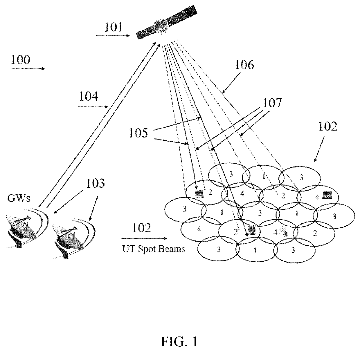
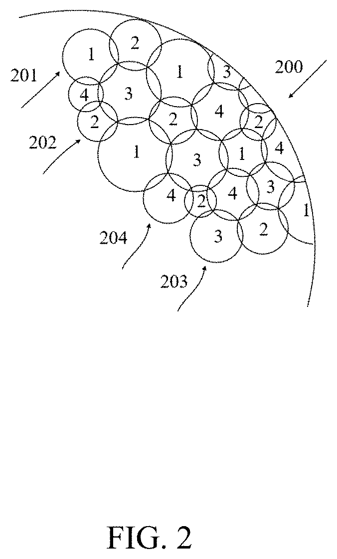
[0018]FIG. 1 illustrates a typical HTS or multi-beam system 100 where the space segment consists of a geostationary satellite 101 and the ground segment includes gateways 103 as feeder links 104 and user terminals (UTs) such as VSATs distributed among the spot beams 102 downlink 105 from the satellite to a UT in a forward link of a gateway-to-UT operation; rays 107 are satellite antenna radiation pattern nadirs that define the signal power peaks measured as 0 dB in the centers of the spot beams while rays 106 represent the satellite antenna radiation pattern n dB apertures that trace out the n dB power contours of the spot beams when they are illuminated by the satellite antennas' radiation power. According to the HTS system architectural elements' denotation convention, the n dB contours of three adjacent spot beams of equal-radius meet at the triple-cross point as illustrated in 106 of FIG. 1 and in FIG. 2, and it is uniquely set.

[0019]FIG. 2 is a detailed sketch of color reuse am...


PUM


Abstract

Method for determining high-throughput-satellite (HTS) system user downlink signal-to-noise-plus-interference ratios (SNIRs) and SNIR distributions is provided, including a procedure for estimating parameters of one spot beam and that for multiple co-color spot beams, and the projection of the satellite antenna radiation patterns onto Earth to form the spot beam power spatial distributions that lead to the SNIRs and SNIR distributions of stationary or mobile user terminals (UTs) in clear sky (CS) line-of-sight (LOS) propagation channel conditions. The estimation precision is controllable. The method is implemented in a programming language run on computational hardware with built-in or connected user interface (UI) devices including desktops, laptops, severs or super-computers. It can be used alone or as part of a simulation package or part of a system operation management software of the control gateway (GW) in the HTS system for system downlink designs.

Description

CROSS-REFERENCE TO RELATED APPLICATION[0001]This application is a continuation-in-part of the U.S. Non-provisional application Ser. No. 15 / 694,167, titled “METHOD FOR PREDICTING SPOT BEAM HIGH THROUGHPUT SATELLITE SYSTEM PERFORMANCE” filed on Oct. 27, 2017 which claims the benefit of priority to U.S. Provisional Application No. 62 / 420,869, titled “HIGH THROUGHPUT SATELLITE SPOT BEAM DEPLOYMENT APPARATUS AND METHOD” filed on Nov. 11, 2016, the contents of which including the amendments have been incorporated into the electronics filing system (EFS-Web).TECHNICAL FIELD OF THE INVENTION[0002]The present invention relates to a communications satellite system's ground segment design and, in particular to the high-throughput-satellite (HTS) or multi-beam satellite system downlink signal-to-noise-plus-interference ratio (SNIR) and / or SNIR distribution performance prediction.BACKGROUND OF THE INVENTION[0003]The HTS system ground segment faces much intra-system interference caused by color r...

Claims


Application Information

Patent Timeline
Patent Type & Authority Patents(United States)
IPC IPC(8): H04B7/185H04B17/336
CPCH04B7/18519H04B17/336H04B7/18513H04B7/2041H04B17/102H04B17/345H04B17/373
Inventor AI, LIPING
Owner AI LIPING
Why Eureka
Try Eureka